Been perusing the other “3-way, non neutral wiring” diagrams provided in some other threads, just wanted to make sure I was in the same boat. My current wiring is summarized as follows:
Power into Light (no-neutral in box) (light is a 13W LED retrofit)
Switch A (Light off)
-White is hot
-Black is hot
-Red is cold (not sure what the correct terminology is)
Switch B (Light off)
-White is hot
-Black is cold
-Red is cold
and
Switch A (Light on)
-All wires are hot
Switch B (Light on)
-All wires are hot
I just wanted to confirm that the diagram provided is still applicable, I’ve ordered the Homeseer Companion switch and the Aeotec bypass since the light is only 13W.
Please let me know if there is any other information or pictures I can provide to help!
So it sounds as if there is only one 3-wire in each of the two switch boxes. Is that correct?
If that’s the case, you likely have a power to the light with the light in the middle. What you are going to have to do is test, USING A METER. Take pictures of the existing connections so that you can put them back if need be. You are going to measure between each of the conductors and the bare ground or the metal box to determine which of the conductors is hot. I’d expect with everything disconnected that only one of the six will be hot.
Also, if need be, can you get to the light box to see the wiring there to confirm?
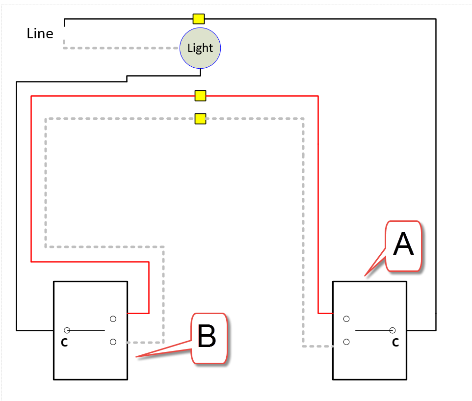
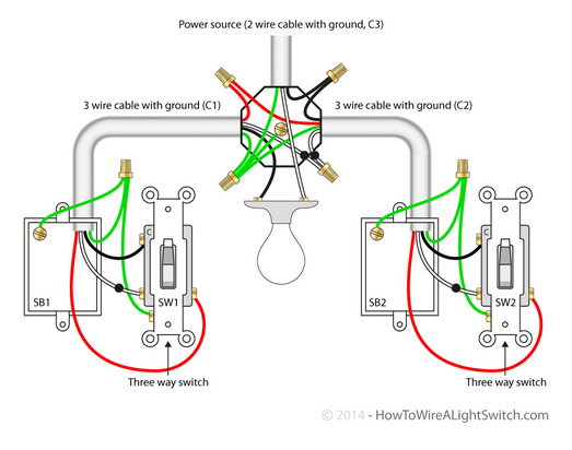
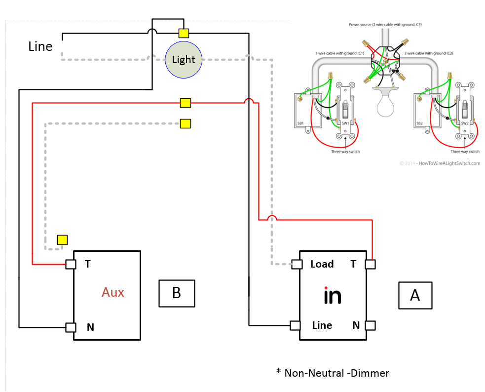
Just checked the wiring in the ceiling, this is exactly matching the diagrams you posted, for the bottom SW2 is Switch A and SW1 is Switch B for the bottom diagram. Top diagram is perfect.
Ok, so this will be a non-neutral with an Aux. Do you have a preference for where the Inovelli goes? The easy install is in box A. Box B may take some rewiring at the light.
Box A was the preferred spot for the Inovelli. As noted in the original post, I ordered the Homeseer companion switch for Box B and the bypass since the light is a 13W LED retrofit.
Right on - so to start for Switch A, connect black to line and white to load. In the ceiling, I’ll have to connect that white/load wire to where the Switch B black wire is currently coming in to the light. First question: where in this do I install the Aeotec bypass?
Once Switch A is confirmed working, connect traveler wire to traveler screw on both Switch A and B. On switch B, connect black wire to neutral position. In the ceiling, “splice” in the black wire from Switch B to the line wire.
Well as expected that went perfectly! Inovelli and AUX switch both working great! The wiring diagram you provided was amazing - had my phone up in the attic with it open to make sure everything was proper.