3 way switch not in provided diagrams

Ok, I have some wiring that does not match the diagrams on the instructions or the ones on the inovelli site.

I have a light that has two switches controlling it. I cannot get to the light to see the wiring there. At each switch, there is only ONE cable going to the switch, nothing going out.

Switch A - black, red, white wire. No other wires, nothing hidden behind the box.
Switch B - black, red, white wire. No other wires, nothing hidden behind the box.
The wires were not twisted nor marked as to indicate what is what. On both switches, the black wires went to the common terminal, the red wire was located at the terminal directly underneath, and the white wire is on the opposite side of the switch.

With all of the wires disconnected from both switches, I found Switch A black wire to be power. Then, with all the wires at switch A wrapped around each other and power back on, I found switch B to have no reading at the black, and the white and red wires to have readings. I was told this means the black wire on this switch is the load, and the others are travelers.

I have the red series dimmer gen 2 and a GE enbrighten add on switch. I was not able to get the switches to work with each other. Out of curiosity, I did wire up the red series as switch A with the old dumb switch as switch B. Switch B is wired as black to common, red below it, white on opposite side of switch.

Do I have a wiring situation that will not work, or will I have to use two red series switches, or will I need to cap off the wires in switch B and cover the wall plate?

I made a poor diagram of what my results were, just incase it would help. When Switch B is flipped down, the black and white show voltage and nothing at the red. In this position switch A has power. When I flip switch B up, only the white has voltage, black and red have nothing - and switch A completely loses power - the light turns off and the LED on the inovelli turns off.

1 Like

It looks like this is your current situation

I have the GE add on switch, however it only has screw for neutral and traveler. So I can connect the traveler, but am confused as to what to do with the other two wires. Do they both get placed in the neutral, or does the load get placed there and the other one capped off?

Sorry I am fairly ignorant when it comes to wiring. While I await feedback I am going to try and cap one off and see if it works.

I tried that, and none of the switches get power.

Is it possible that I need to connect both the white and black (load) onto the same neutral connection of the add on switch?

I haven’t flipped the power on yet, but in my above diagram with the dumb switch, the dimmer was only getting power when it was flipped down causing the black and white to have power.

Here is a really good reference. The more I think about it, the more I’m inclined that you are going to need to get to the wiring in the fixture. The last two diagrams on this page is what your most likely looking for.

1 Like

Nooo do not hook up all 3 wires to the Aux!

Only did to clarify my question, breaker was off ! I cannot for the life of me figure out how to get these to work with how my wiring is setup. I think I am going to have to figure out how to get to the light fixture to see what the wiring looks like up there.

Thank you for all of your input! I am going to go to bed and wake up fresh tomorrow and hopefully figure out how to get to the lightbox and see how it is wired.

1 Like

It seems like you have a 3way with source at the light. You have a multimeter to confirm LINE?

He does have a power to the light situation, but it’s not that diagram. So that solution won’t work.

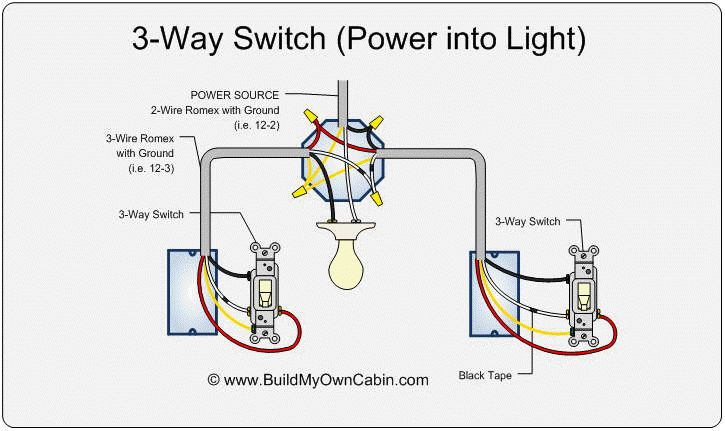
@dc77 has a single 3-wire to each box. That means that power is to the light, but there is no Romex connection between the boxes. Instead, there is one 3-wire from the light box to each switch but nothing between the switches. From what @dc77 described, this diagram is correct:

There is a way to wire this, but unfortunately, it involves re-wiring at the light. From the light box, you have to send power and a neutral to one switch were the Inovelli will go. From the light box you also have to send power and one traveler coming from the Inovelli to the other box where the Aux will go.

It looks like this:

1 Like