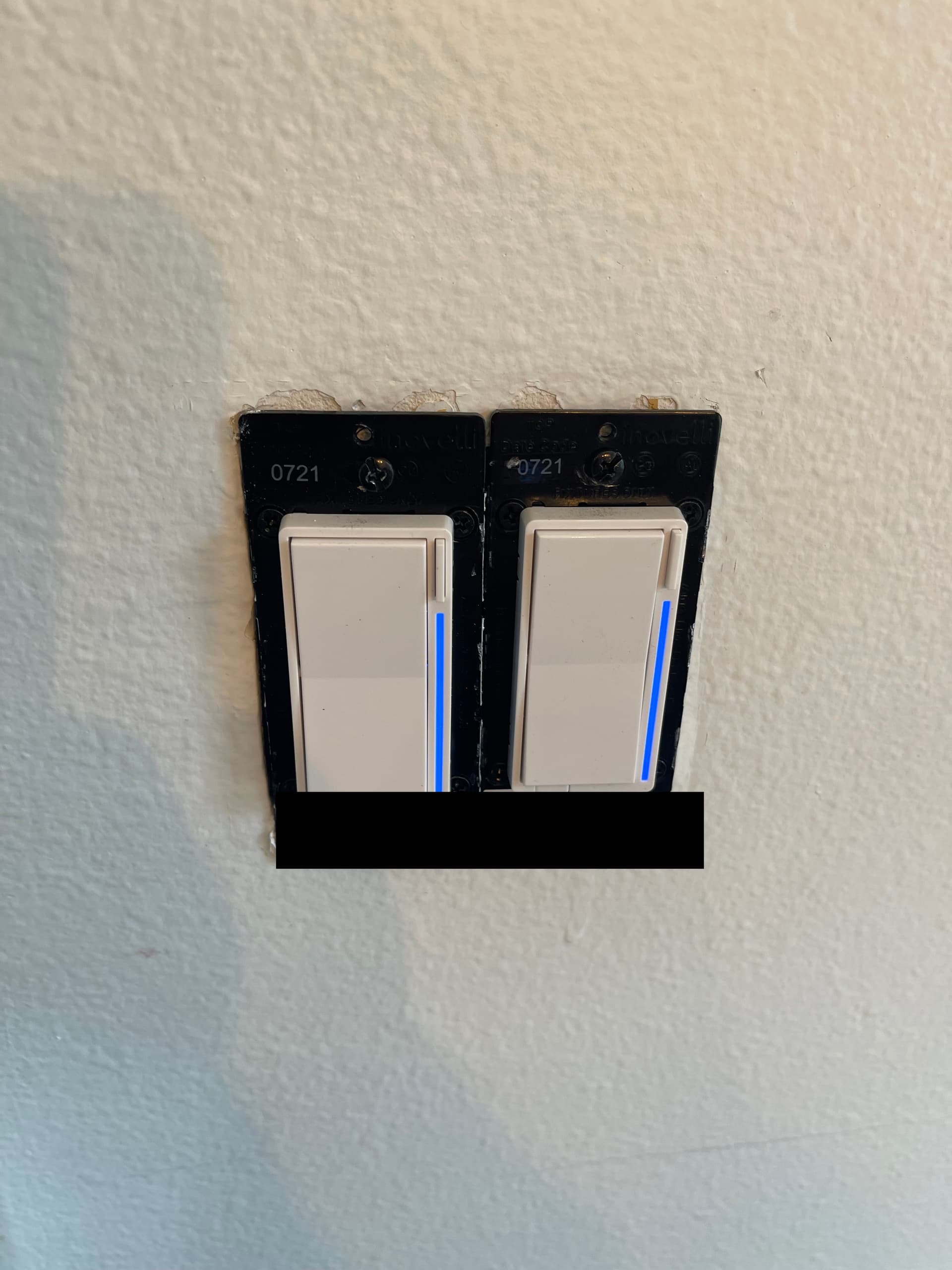
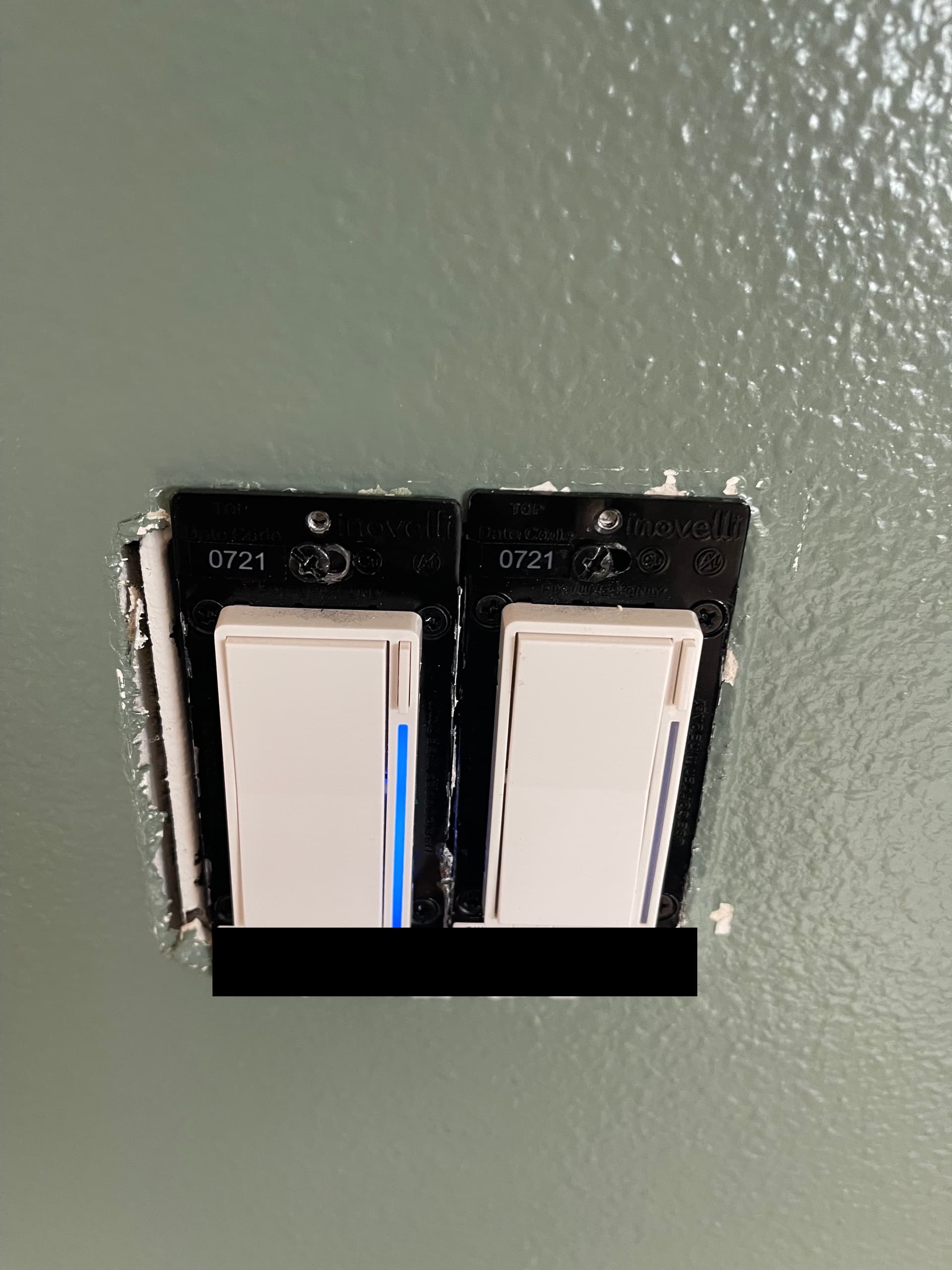
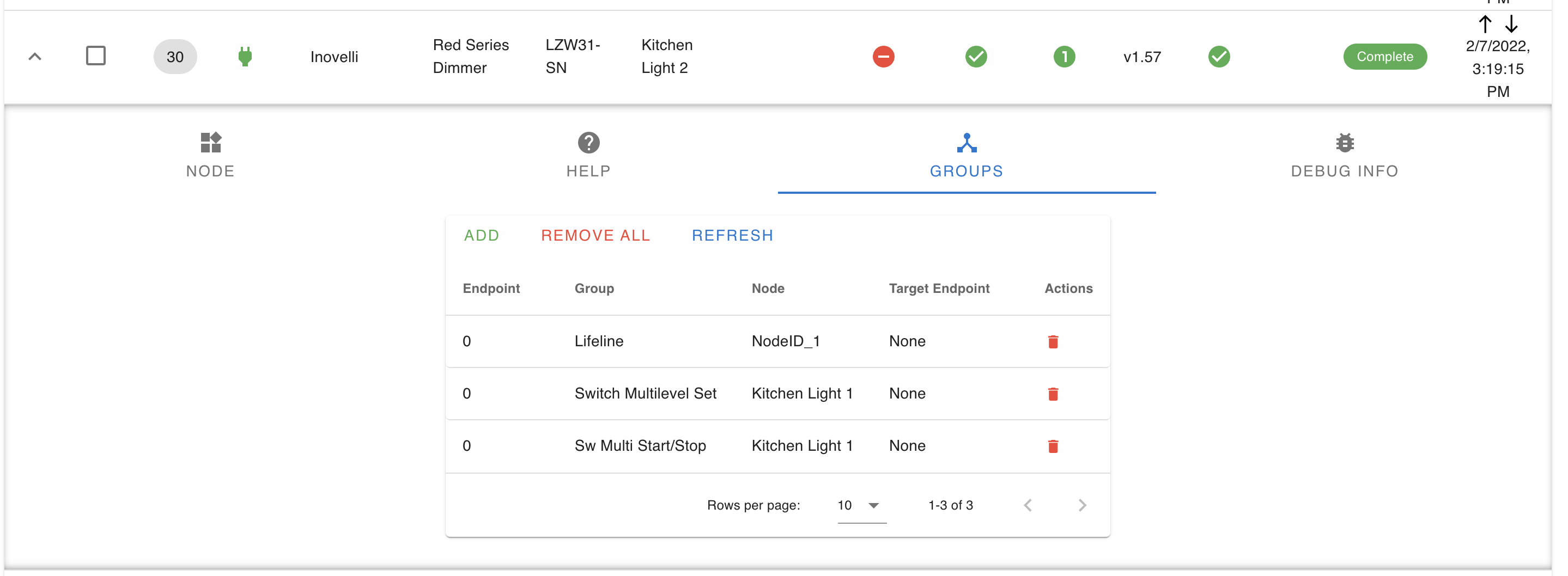
If I turn the lights on from “Kitchen 2” the LED indictor will go up and show that “Kitchen 1” is on also. And I can also turn “Kitchen 1” off from “Kitchen 2”. The LED indicator never changes on “Kitchen 2”, but I am pretty sure this is normal if I’ve read everything correctly.
The lights are 6 can lights in the kitchen. I put the old toggle switches back earlier today to make sure things were still working, and they were. But no matter what I do, I cannot even get the lights to turn on with the 2 smart switches.
If anyone has any ideas, or sees something I did wrong I would really appreciate the help.
So my suggestion is that you implement this in stages. Start off by making sure that the load switch (Kitchen 2) is working as a normal 2-way. Then after that is working fine, you can configure the associations. If I understand you correctly, the Kitchen 2 switch as a 2-way won’t turn the light on.
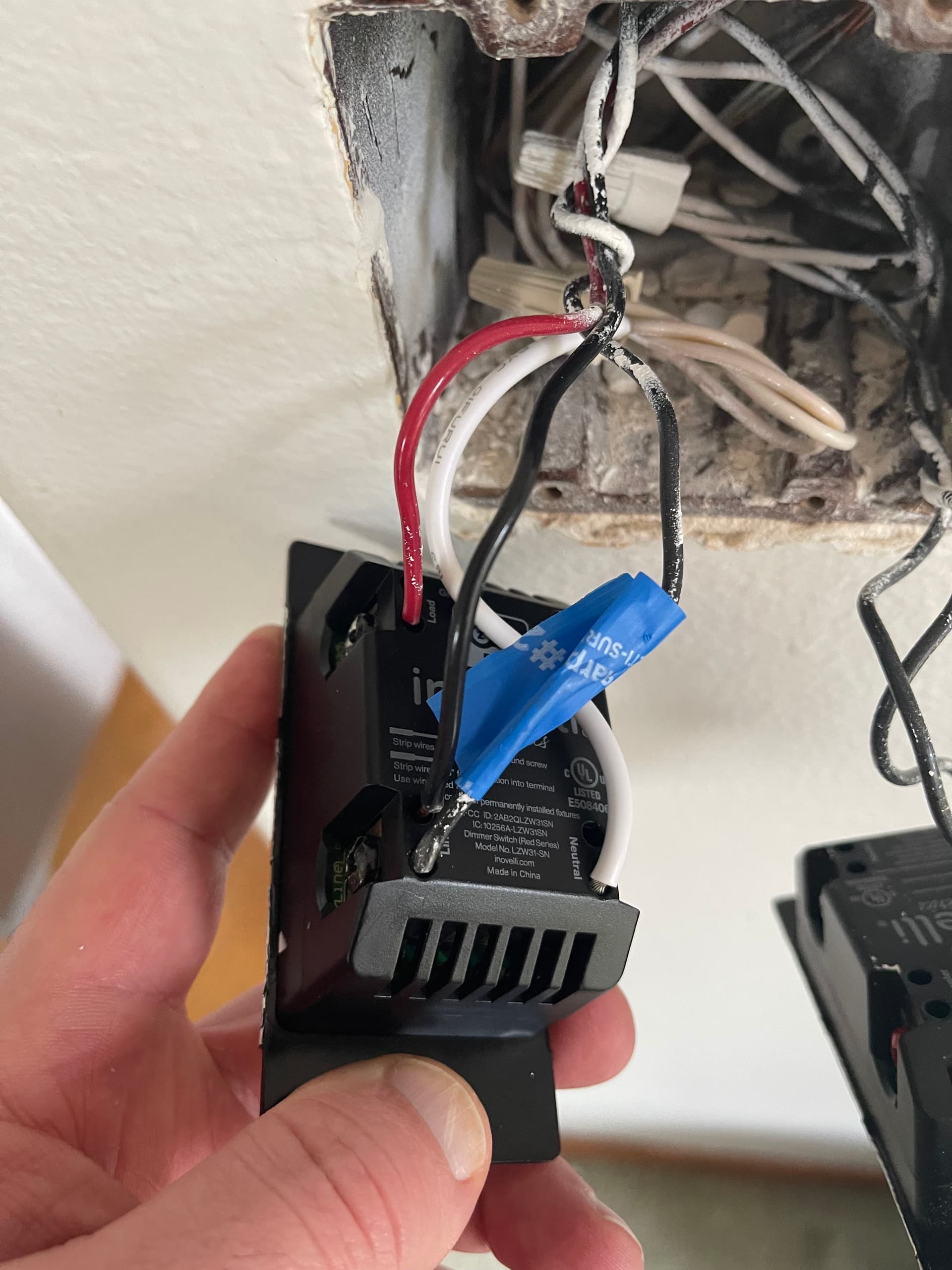
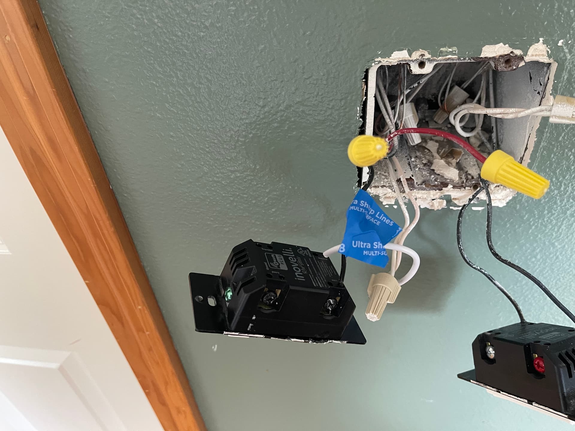
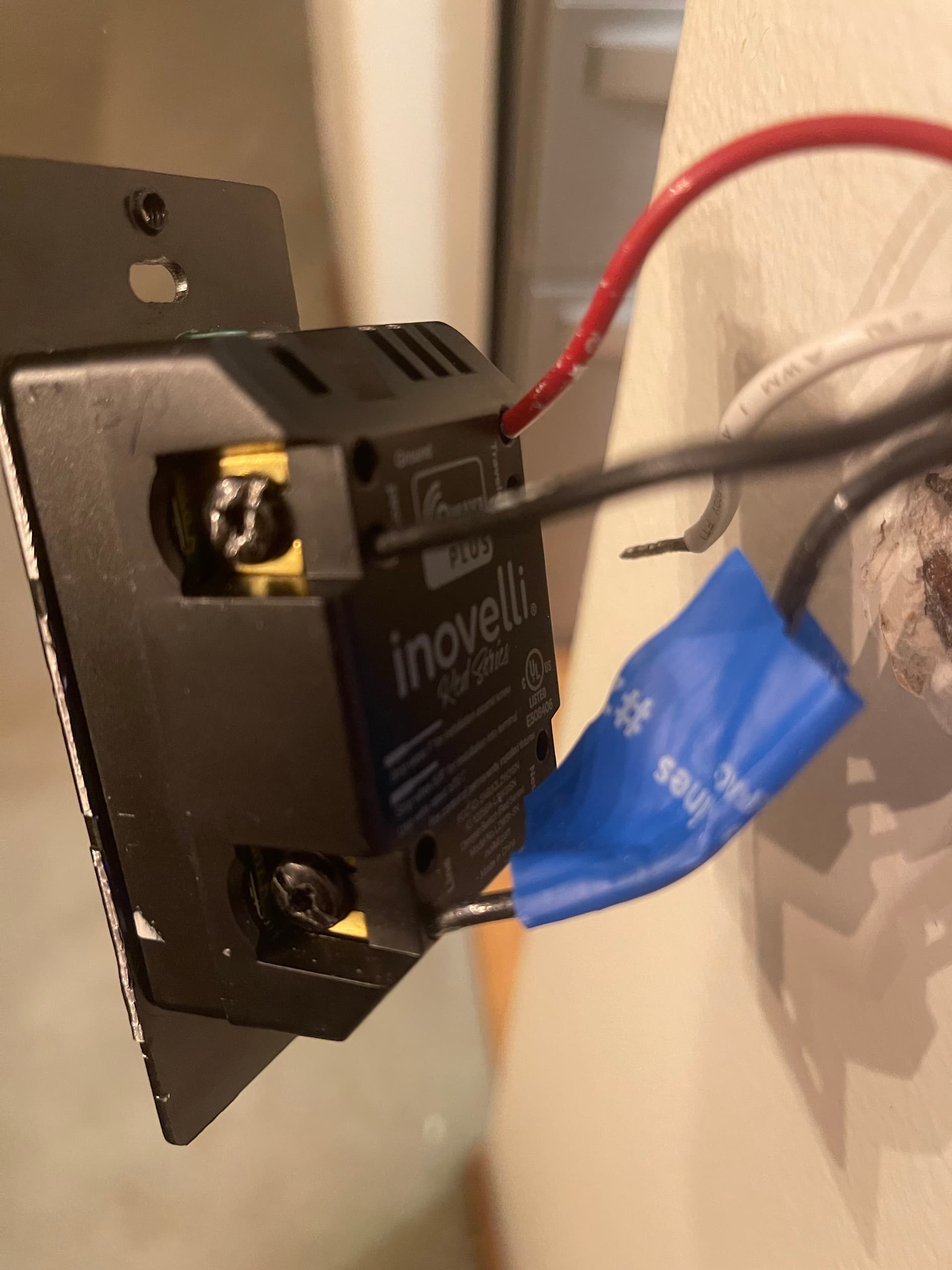
It’s hard to tell from your pics, but generally the load going to the light is via a 2-wire. So if I’m understanding correctly, that 2-wire should be in your Kitchen 2 box. But your Kitchen 2 pic shows a red conductor connected to the Load terminal. I’m guessing that’s from the 3-wire going to the other box.
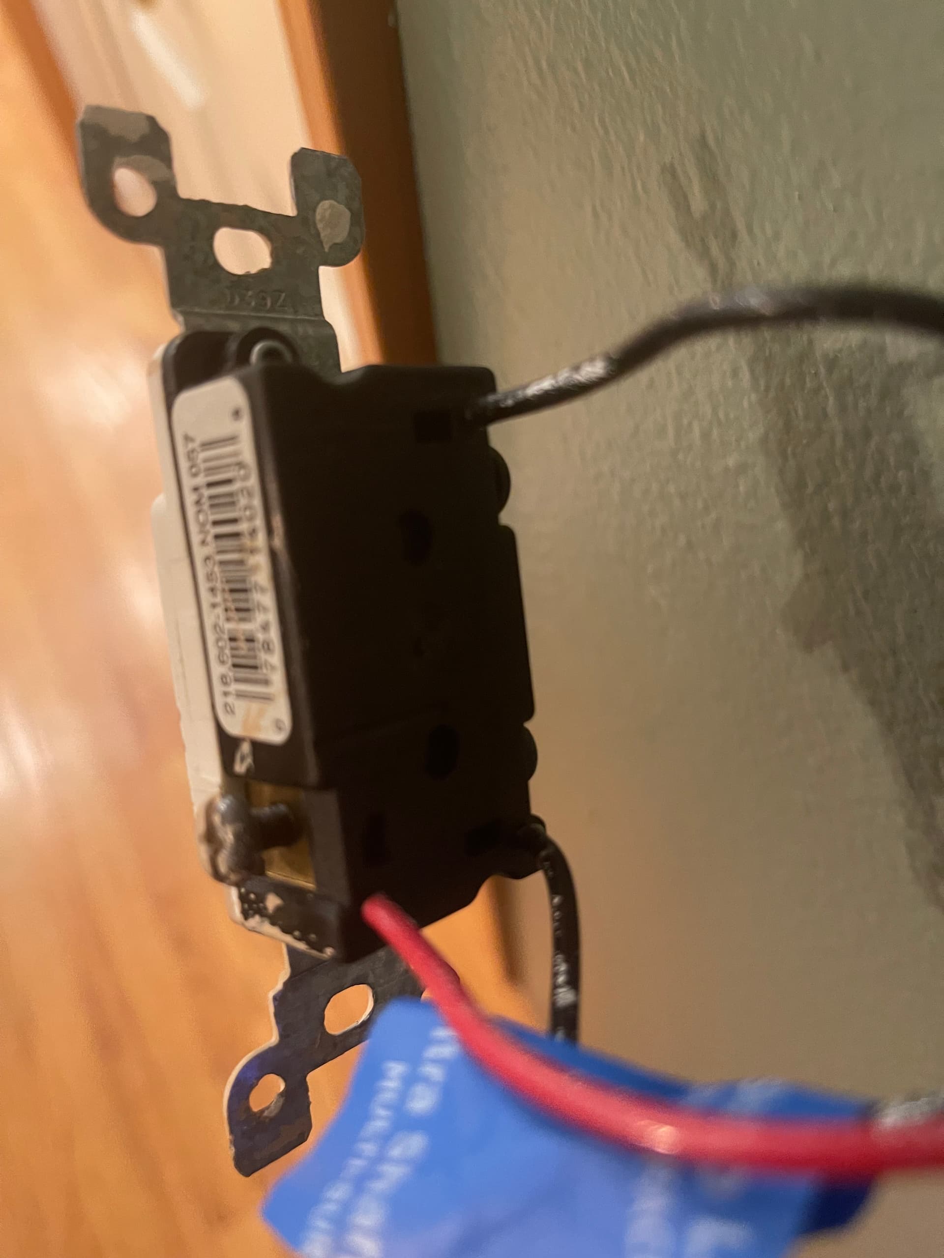
More than likely, the load conductor would be the black from a 2-wire that was connected to the black screw of the dumb switch.
If you have a load between the boxes (aka load in both boxes) where your light(s) is in between the two switches, then the load won’t be a 2-wire to the light. Take a look at this diagrams and identify your original wiring scheme:
Thanks @Bry. I thought that my current wiring was Line/Load in separate boxes, but I disconnected “Kitchen 2” and wired “Kitchen 1” as a normal 2-way switch, and it didn’t work at all :\
And yes, from “kitchen 1” box, there was a common, and a black traveler, and a red traveler. Then in “Kitchen 2” box there is the same black traveler and red traveler coming from “kitchen 1” box, and a wire going to the fixtures.
On the dumb toggle switch setup it was:
“Kitchen 1”
Common wire on black screw
Red, and Black travelers on the other two posts
“Kitchen 2”
Load switch on black screw
Common, and red traveler on the other two posts
I was able to wire “Kitchen 1” Inovelli switch as a typical three way switch, and put the dumb switch on “Kitchen 2” and turn the lights on, but the toggle on “Kitchen 2” has to be in a certian position for it to work. Not sure if this helps or not.
“Kitchen 1”
Sort of, but not really, lol. But I agree mapping what you have out is the first step. It might help if you put the 2 dumb switches back in working properly.
So with a line and load in different boxes, there will be a 2-wire and 3-wire in each of the boxes. On the panel feed side, you’ll have a 2-wire hot and neutral and a 3-wire that runs to the other box. The hot black of the 2-wire is connected to the black screw of the switch. The white is connected to the white of the 3-wire to send the neutral to the other box.
In the other box, the 2-wire black is connected to the black screw of the switch and goes to the light, along with the neutral.
So when you are diagnosing this, remove the black conductors from each of the black screws of the switches. Using a meter, test between the disconnected black conductor and the white bundle. Only one pair of those will be hot. That is the panel side.
So for what you’re trying to accomplish, in the “panel” box, connect the hot and neutral to the Inovelli. Connect the black and the white from the 3-wire to the other Line and Neutral holes on the Inovelli. Cap off the red.
In the other box with the load, connect the black and the white from the 3-wire to the Inovelli. This is a hot and neutral and will power it. Connect the black from the 2-wire load Romex to the Load terminal on the Inovelli. White from the 2-wire goes to the other Neutral hole. Cap off the red.
Factory reset your switches, then configure this non-panel Inovelli as a 2-way Neutral and it should work as a 2-way, although that is the default after a factory reset.
Once that is going, then associate to get the “panel” Inovelli paired in.
In your last picture of kitchen 2 you have 2 black wires connected to the switch. One of those is likely the load and the other is the traveler you turned into the line conductor from Kitchen 1 by hooking it to the line terminal of the Inovelli. I don’t see this wire in your first Kitchen 2 picture but maybe if is under the cap on the left?
In your first wiring pictures, you connected the red to the load terminal in Kitchen 1 and that simply fed power over to the capped red wire in Kitchen 2.
I’m guessing there is a 2 conductor cable in Kitchen 2 that is the load. You can likely put the black of it to the load terminal on that device and cap the red off making the Kitchen 1 device the one without a load.
I also think you set them wrong.
On one of the devices find this parameter and set it to disabled - [17-112-0-12-4] Association Behavior: Z-Wave Hub. The secondary device you won’t use for any automations and such is the best choice for this, but I haven’t seen anything to say it actually matters which one.
In the associations for both devices, associate group 2, 3 and 4 to the other device.
Thanks @PJF. I was correct that my wiring is Line/Load in separate boxes, but you were right that I just needed to cap off the red traveler in “Kitchen 1” and hook up the black traveler to load in “Kitchen 2”
As far as grouping, I only needed to associate group 3, and 4 on both devices. And of course disable relay on one of the devices too.
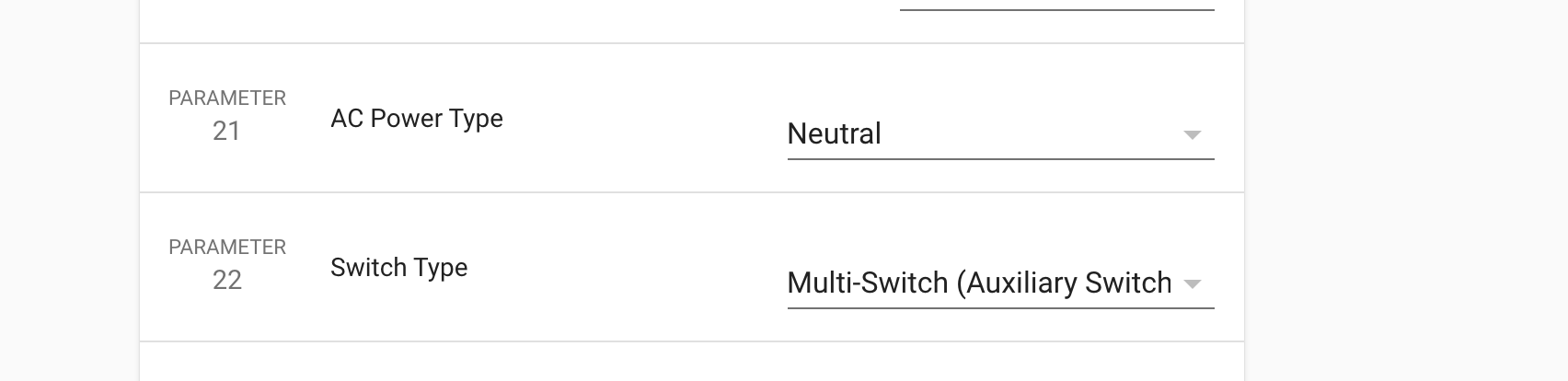
I should note also. On both switch setting parameter 21 “AC Power Type” to “Neutral” helped to fix lights not being fully bright, and On my panel switch(kitchen 1), I also had to set Parameter 22, “Switch Type” to “Multi-Switch”