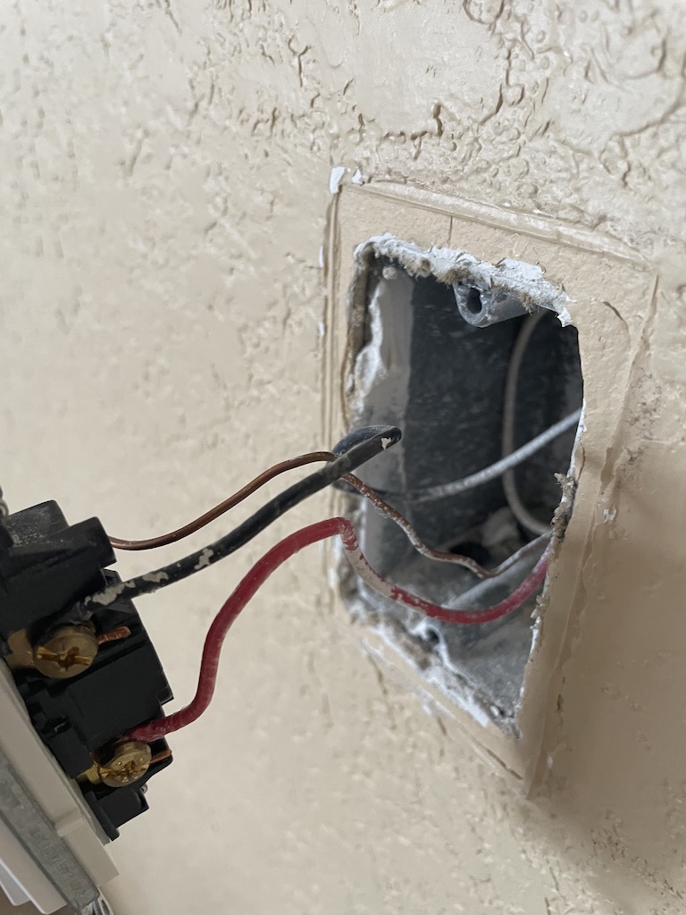
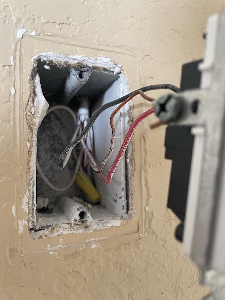
Pulled out my switch today to see what I was up against and it wasn’t wired the way I expected it to be. Its a single pole switch running the fan and light at the same time (fan is a older remote model which I am hoping has a removable RF module that I can swap out once I get to that point).
Photos attached of what I’m seeing. There is a red, black, white wire coming in. Red and black are hooked up to the switch. White is capped.
In my every learning mind I am thinking that the power for the fan is at the fan side of things since the switch box only has one wire coming in?
I think the thing that’s got me confused is the red wire. Im not sure why its there and why the white (assumed neutral) is capped?
Do these photos tell anyone if I am even going to be able to use the light/fan switch in my setup?
I havent pulled apart the fan itself as of yet which of course would probably tell us more!
My best guess is LINE is at the fan and a 14/3 wire was ran from the Fan to the switch box. They used BLK and RED to send LINE to the switch and back up to the fan.
We’ll need confirmation with pictures at the fan box though.
If confirmed, I would rewire the fan box and keep line/neutral at the canopy and pigtail the BLK and WHT 14/3 that goes to the switch box line/neutral bundle for the switch line and neutral.
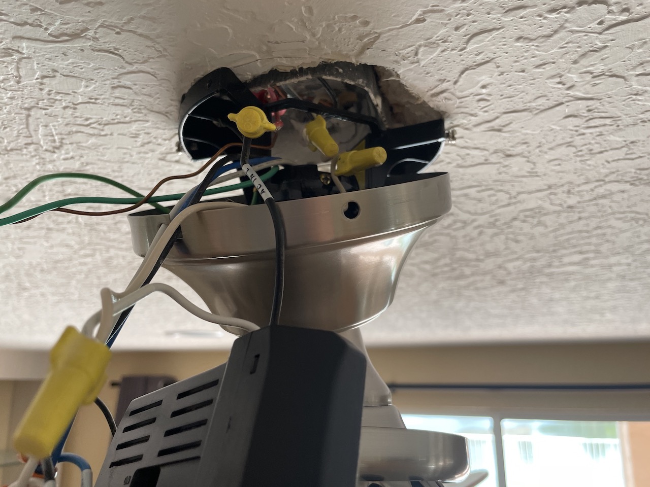
Ok so I got into the fan canopy and I think I understand what to do but wanted to run it by here just in case.
Images attached but what Im seeing is a 2 wire coming in, WHT & BLK. A 3 wire going out, WHT, BLK & RED.
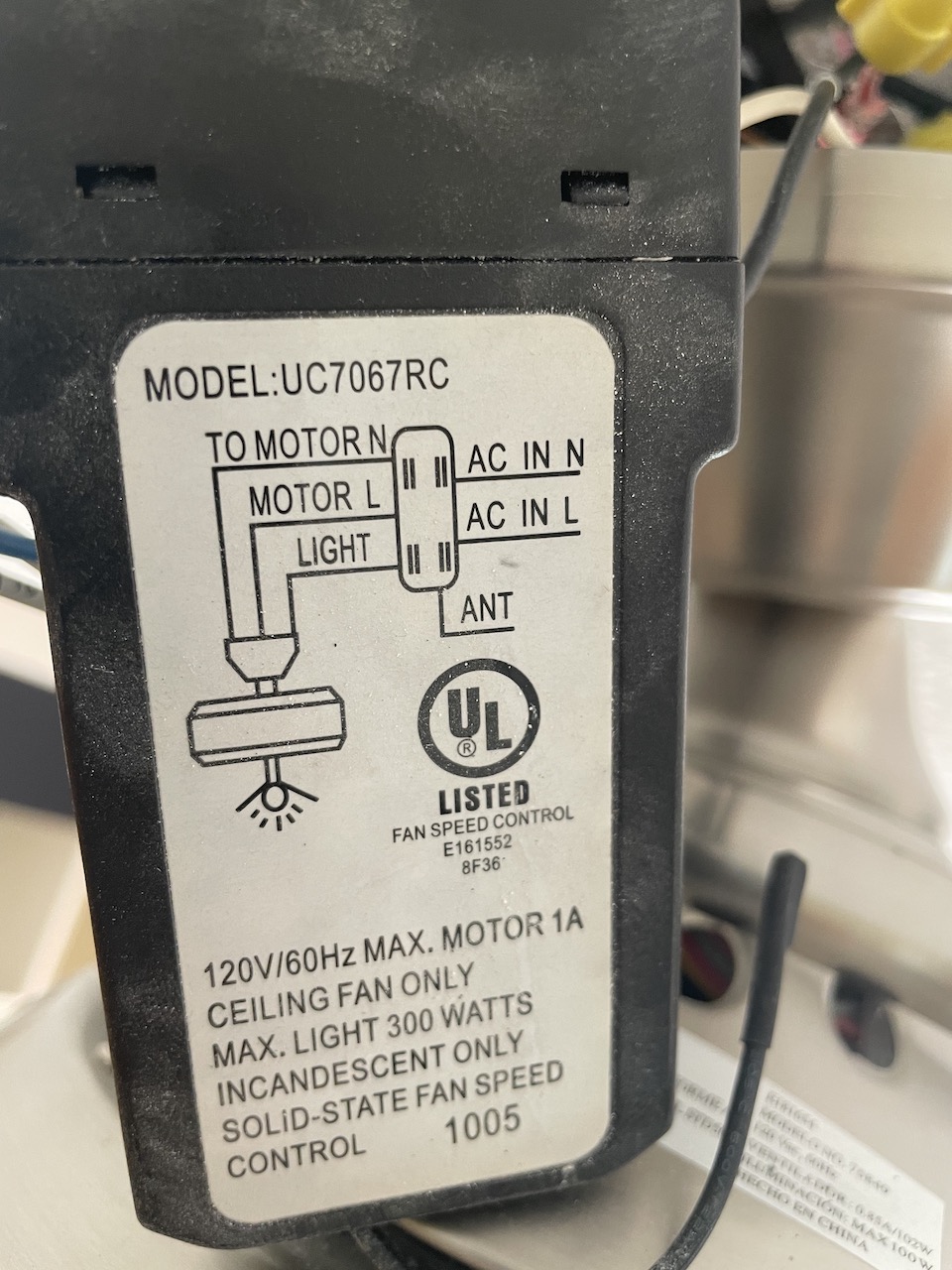
The BLK coming in (assume line/hot) is nutted to the BLK going out to the wall switch. the white coming in is nutted to the white going out and also the “AC in N” on the old receiver.
The red going out is nutted to the “AC in L” on the old receiver.
Would the Inovelli wiring diagram for a fan with power coming into the canopy using no pull strings be what I want to use?
Correct. Obviously the drawing doesn’t capture your old receiver.
Just make sure you’re sending LINE/NEUTRAL to the Switch box for the switch.
Make sure you capture the NEUTRAL bundle which has pigtails to the switch^, canopy, AND fan. Some people forget neutral is not provided to the fan via the canopy.
Wiring it exactly like the Inovelli schematic would power the module and light at the fan as it was pulsating in an attempt to pair with the switch but the switch itself didn’t seem to be getting power? I ended up hooking the red wire back up, tying it into the neutral bundle at the canopy and attaching it to the neutral terminal on the switch.
Wonder if there is something physically wrong with the white wire of the 14/3 going from the fan to the switch and they used the red as a neutral?
I just left what should be the correct white neutral tied in so at this point there is no way to know for sure as I sure as heck not unhooking everything just to test out that theory!