Hey all! Ok, time to make some replies – sorry, been super crazy busy with making PPT’s for investors. Hopefully the light at the end of the tunnel is near.
Yeah, I do think this is really cool as well – I do agree with @harjms and @DROCK_IN_NC in that it can be a hassle. I also struggle with my kids and the Brilliant switch lol. But, I do really like the look and aesthetics of the slider!
My bad ![]()
We’re hoping to – I’m not quite sure how we’ll pull this off yet as the aux switch will have limited, “smarts” in it. Possibly it could be pulled off with an MCU of some-sorts, but that’s beyond my pay-grade lol.
I’m not too sure on this debate. We have a discussion with the manufacturer next week and we’ll try to better understand.
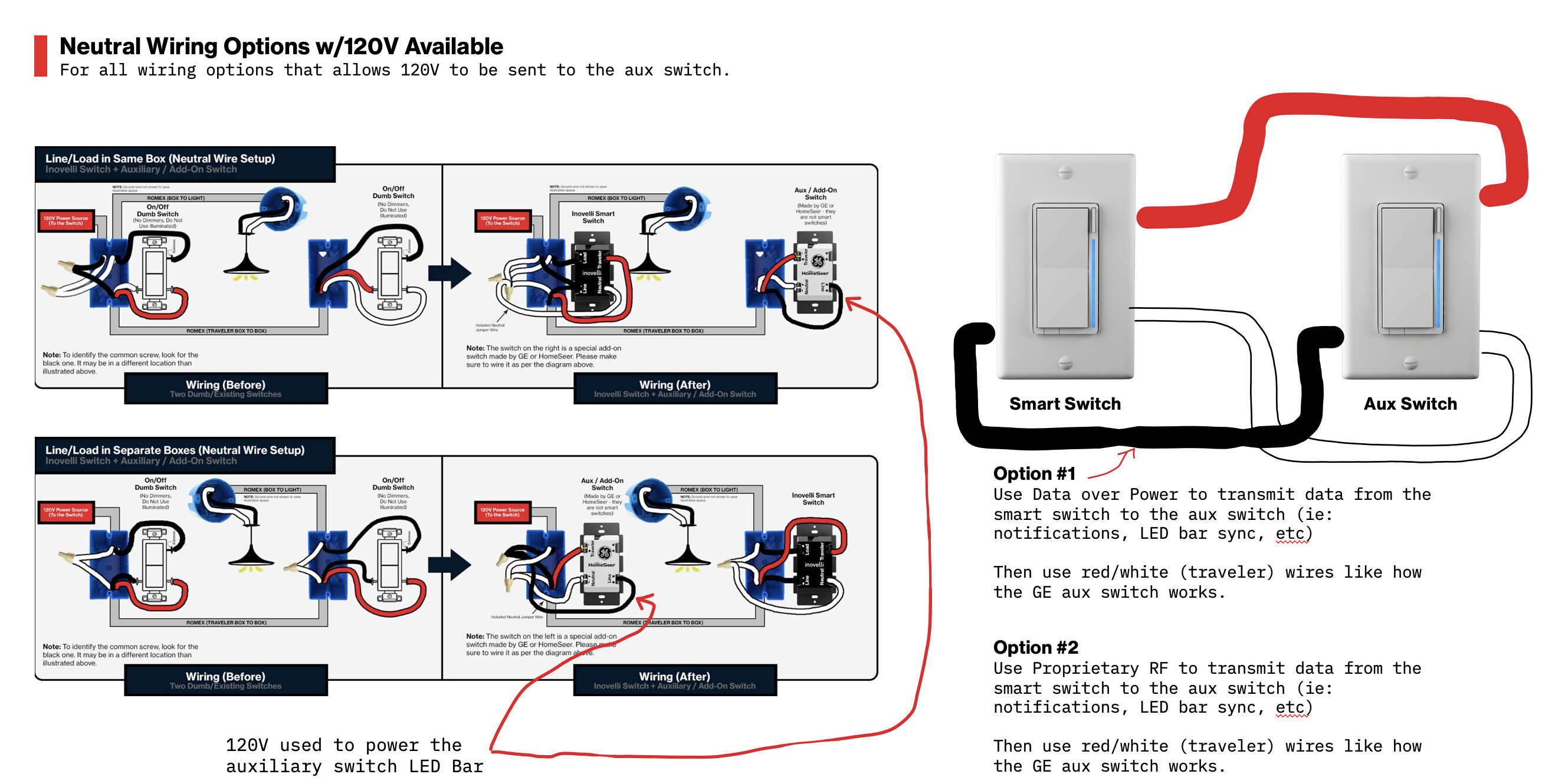
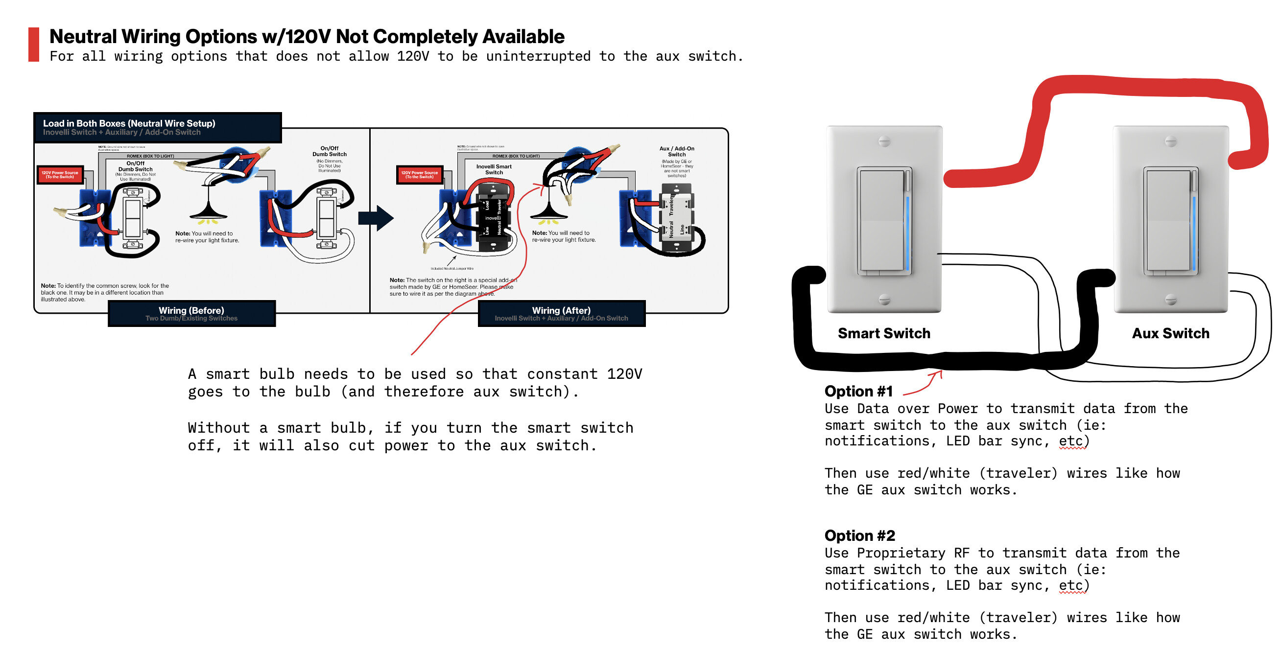
Question for you guys though – what if we put a 3rd terminal on the aux switch that acted as a constant source of power? I really only know the basics of electrical, but could we just do something like this:
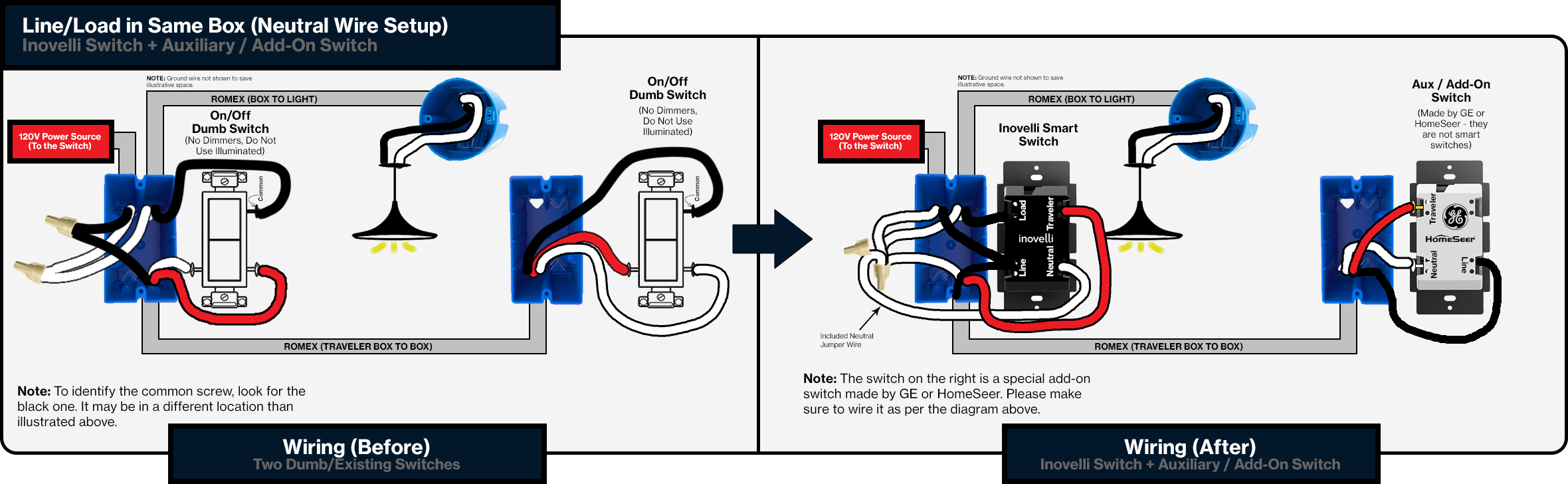
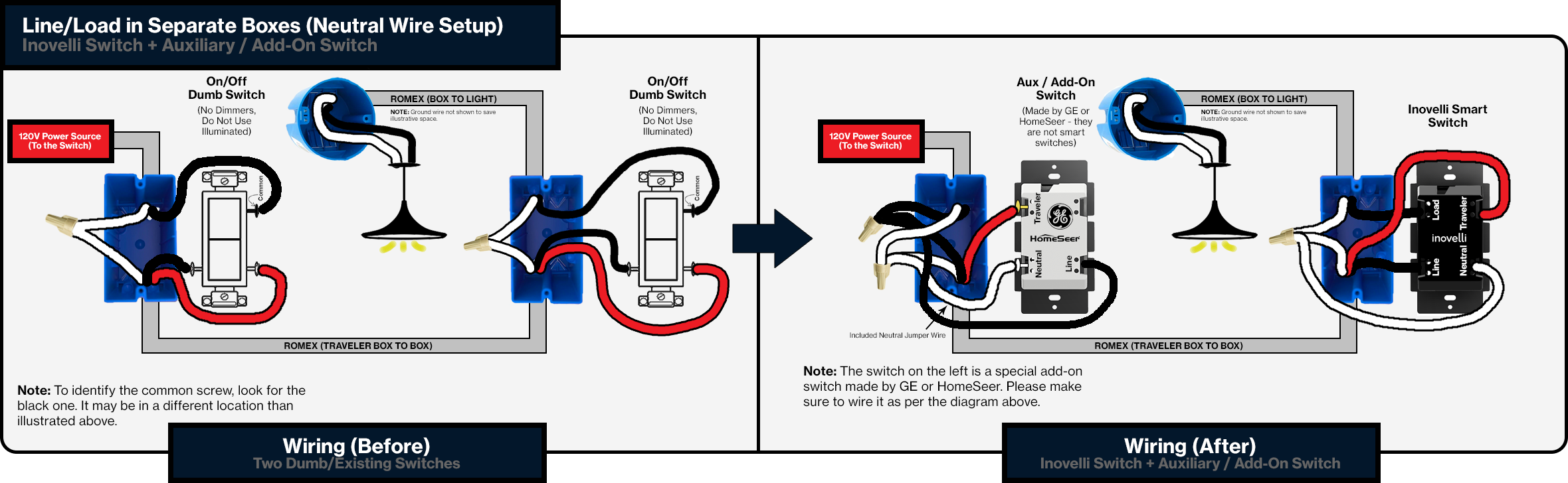
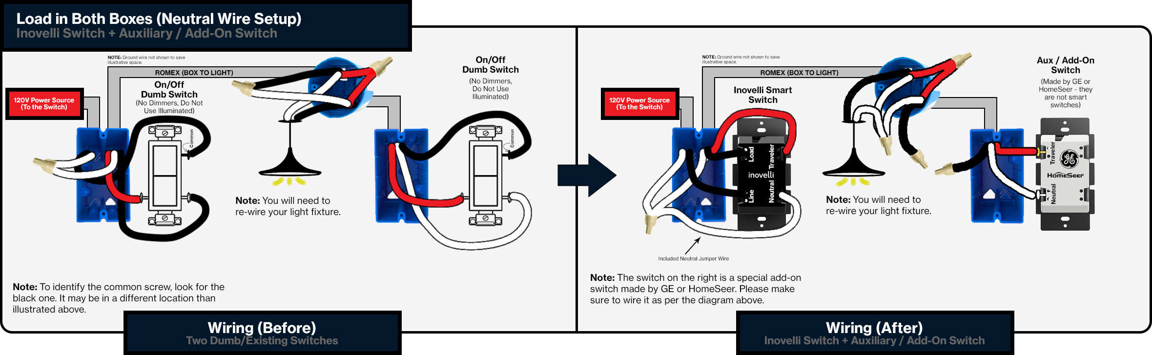
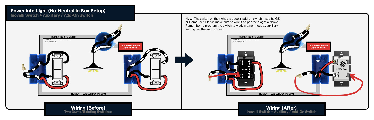
Non-Neutral:
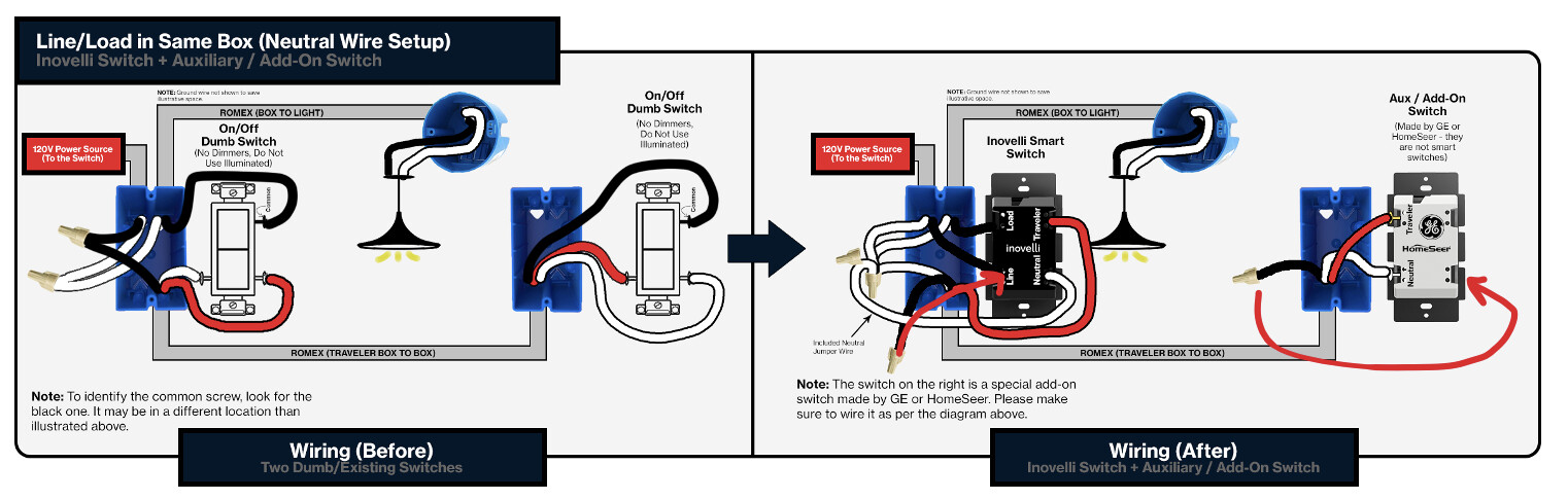
Neutral:
Somehow have the PCB use the constant line to power the LED bar and, “smarts” whereas the travelers would detect paddle presses as normal?
Quoting you again lol my bad – can you let me know what your exact setup is (ie: GE Enbrighten + Hubitat)? This way we can mimic it. We tried with our current manufacturer to get this to work using the quick change in voltage/current/etc but the variances were too small for the smart switch to detect.
So, we’re curious on how GE’s and HomeSeer’s does this. We do have the other manufacturer (who’s making ZigBee) working on this feature though and they’re the ones building the aux switch.
Excellent question – the limitation here is the smart switch, as much as it pains me to say. Our current Z-Wave switches do not have the capability to work with non-Z-Wave smart bulbs in a 3-Way setting (to my knowledge, I’ll have to check with @EricM_Inovelli – we may have fixed this).
Think of an auxiliary switch as a non-smart switch that acts more like a momentary switch. Through the traveler wires, the smart switch can detect the current/voltage (I can’t remember what we use) change and it adjusts the load accordingly.
The way it works with Z-Wave (and possibly non-Z-Wave, I really can’t remember) is that when the relay is locked on the smart switch, it interprets the voltage change from the aux switch and says, “no, don’t manually dim these bulbs, but rather send an Association command to the Z-Wave bulb to dim digitally”.
Hopefully I’m making sense lol.
Let me double check with Eric M on non-Z-Wave bulbs, and if the smart switch does support this, you should be able to put Project Golden Rule in there (and also GE/HomeSeer aux switches now).
Unfortunately, not… another limitation with our switch. Dangit lol.
The only way to get this to work would be by installing a separate fan/light switch and associate them together via Z-Wave. We will also be working on a remote once funding comes in that would solve these problems as well. It would actually solve both your #1 and #2 question. Hopefully we can get this out quickly!
 ). I await your followups whenever you get them. It’s ironic, I have 3 other spots that each are 3-way setups, but luckily, for all of those I have no desire to install smart bulbs nor do they possess any tricky characteristics to them
  !
!