EDIT: This project had to be put on hold, but has been replaced with this one: Auxiliary Switch | Project Golden Rule (Non-LED Version)
TLDR: Here’s the PRD (Project Request Document) that we used to kick this off – this will give you the highlights and has pretty pictures.
Project Golden Rule - PRD.pdf (715.0 KB)
NOTE: This is a PDF version, the PPT version is live and edited so the PRD may change and thus so will the project. However, I may not update the PDF as it shouldn’t change too much. In other words, this is a disclaimer stating that what you see in the initial PDF may not be what’s final.
Project Team
Feel free to tag any of us with questions. Courtney & Darwyn are the go-to’s for overall project management and timeline questions, Eric M is the go-to for any firmware related questions and I’m (Eric H) the go-to for anything else. Either way, we’re all here to help!
- Project Manager (Inovelli): @Courtney_Inovelli
- Project Manager (Manufacturer): @Darwyn_Inovelli
- Innovation Lead: @Eric_Inovelli
- Technical Lead: @EricM_Inovelli
Introduction
As per our tradition of working with you amazing people, here’s what this thread allows us to do as a community.
- Allows us to keep everyone updated on the project status (either good or bad)
- Allows you to participate and help us develop amazing products together
- Enjoy each other’s company and have fun talking home automation
How this initial post will be laid out is in five sections:
- Project Overview
- Initial Hardware & Software Requirements (edited to remain up-to-date)
- Timeline (edited to remain up-to-date)
- Pinned Ideas & Shout-outs (edited to remain up-to-date)
- Weekly Recap
Housekeeping
- DATES & FUNCTIONS ARE NOT SET IN STONE: Just a reminder that all dates and functions are sometimes fluid. We have to make choices based on feasibility, opportunity costs, and overall timeline. I will be as transparent as possible on these decisions, but just a heads up, they may not always be exciting.
- NO IDEA IS A BAD IDEA: Ok, some are, but honestly throw out anything that you can think of. If we use your idea, we’ll credit you and send you a free device, so take that shot!
- VERSION 1 VS VERSION 2: Some ideas may be fantastic, but may not make the cut for the first version of the product. Once the product is locked in from a function standpoint, we’ll keep a tally of V2 ideas and then once the product is produced, we’ll move the ideas over to a suggestions/wishlist section.
Ok, let’s get this party started!
Project Overview
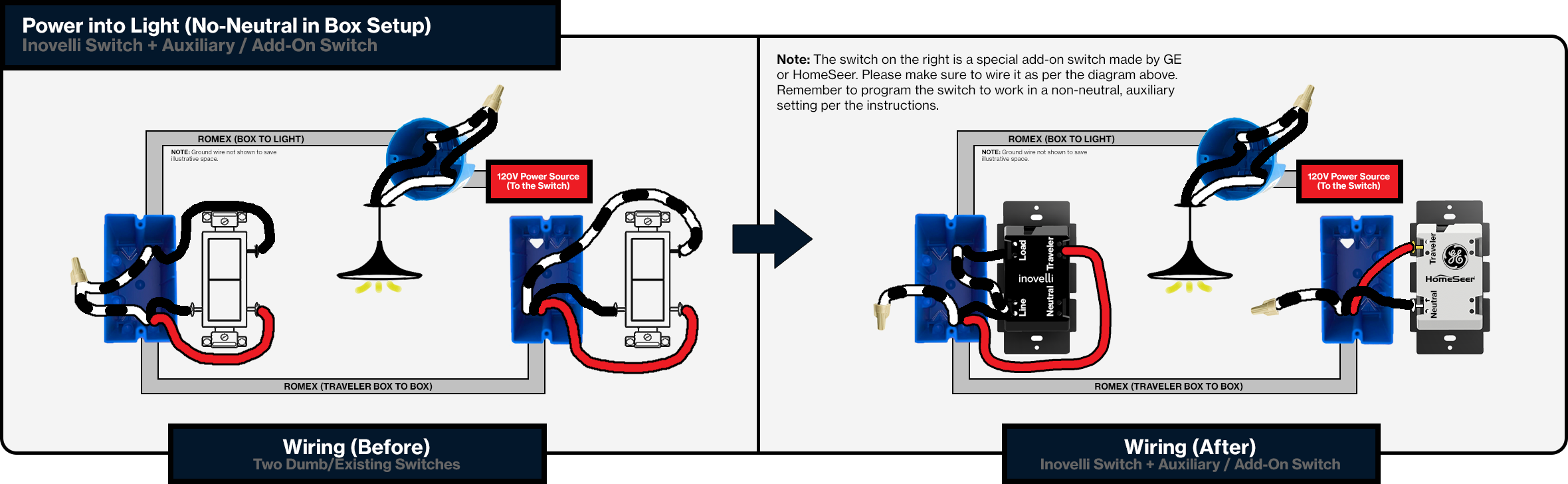
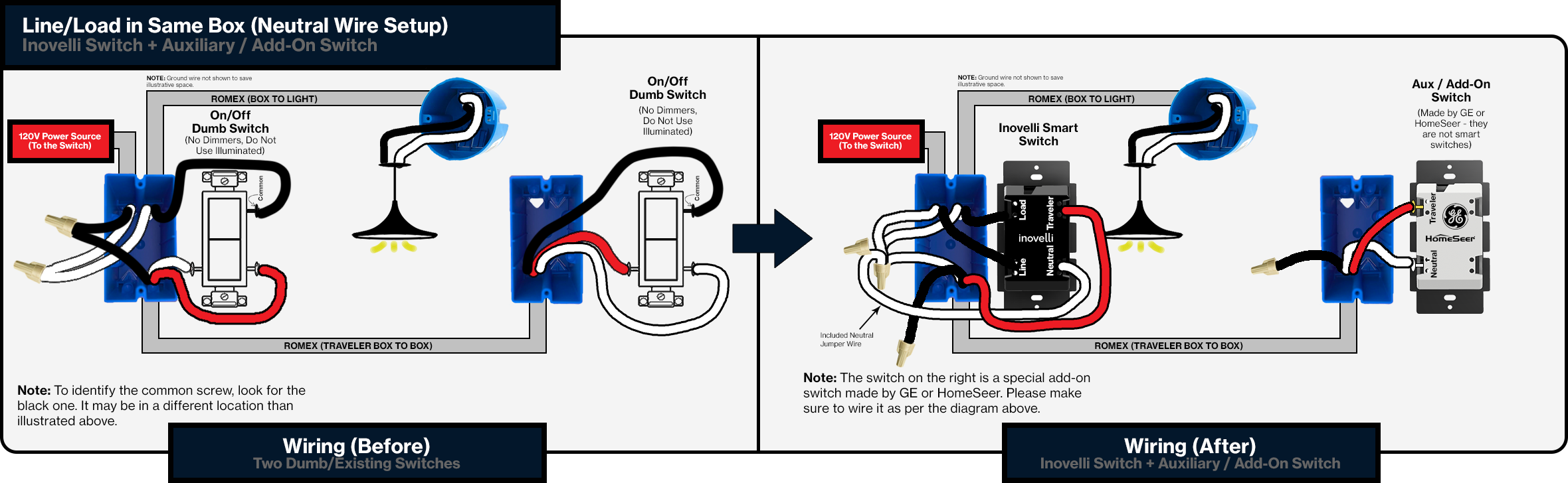
The purpose of this project is to give people an auxiliary switch that matches their main, smart switch. Currently, customers have to purchase GE, Honeywell, or HomeSeer aux switches if they want dimming at both ends of their multi-way setup.
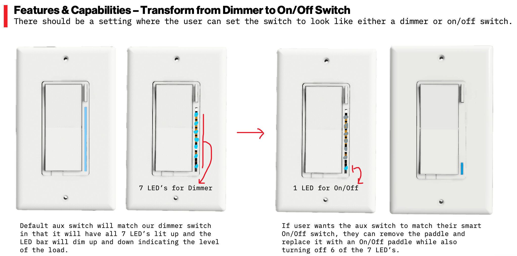
In addition, we need a switch that spans across our Z-Wave and ZigBee options from a unification standpoint. Not only that, but one that looks like either an On/Off or Dimmer. Quite the challenge!
Project Name - Golden Rule
Everyone knows the, “Golden Rule”, which is to treat others the way you’d like to be treated. The same concept applies here in that whatever you do at the auxiliary switch is how the smart switch will act. In addition, there’s a funny SNL skit (NSFW) about the Golden Rule and 3-Way’s (wiring of course), so we thought we’d play a little double entendre.
Golden Rule - Hardware Requirements
We will be using our current dimmer switch hardware with a few modifications to allow for you to also present this as an On/Off switch.
Hardware
Hardware - Dimmer Switch (Look / Feel)
- Responsive Paddle: rests in a neutral state (tap up = on // tap down = off & hold up = dim up // hold down = dim down)
-
Config / Favorite Button: button should be used for configuration of the switch as well as scene control.
- Should be able to be held (for config)
- Should be able to be tapped (for scene control)
-
RGB LED Bar: should measure the % of how much the switch is dimmed
- LED’s should be RGB (artificial white included)
- LED’s should also be able to be dimmed
- Colors: dimmer switch will be offered in white (matching Lutron Claro wallplates), but the paddle should be able to be replaced to change colors (almond, brown, red, black, grey, etc)
- Slim Design: depth of switch should be as slim as possible so that it can fit into metal boxes.
- Air Gap: UL requirement
- No heat-sink tabs: remove heat sink tabs for easier installation (note: may have to sacrifice max wattage)
Hardware - Features & Capabilities
The big issue here is that if we have the LED bar, it’s highly unlikely that this switch can be used in a non-neutral setting as it needs to have power to power the LED bar as well as the IC chip inside of it.
I don’t think there is anyway around this. More to come as we enter into the R&D phase, but this is what we were initially told.
Golden Rule - Software Requirements
Keep in mind this is NOT A SMART SWITCH but rather a momentary style switch that relays onto the smart switch via the traveler wires.
However, there does have to be some, “smarts” in it to change LED bar colors, config itself to work as an On/Off or Dimmer, and potentially to send scene commands (not actual Z-Wave/ZigBee commands, but possibly an interruption in power signals to the smart switch).
LED Bars in Dimmer setting should sync to the Smart Switch (thanks @jtronicus!)
Timeline
Ah, everyone’s favorite part. When is this flippin thing going to be released? Great question – here’s the high-level of what happens leading up to the first release of the timeline:
- We present a PRD (Project Request Document) that has all of the above info in it (see above section for the pdf)
- R&D (manufacturer) analyzes the PRD and we go back and forth until we can align on 90% of the product
- Initial Timeline is released and remaining 10% of product features are added/cut along the way
Again, just want to throw this out there – I don’t have a crystal ball so I can’t predict things that come up along the way. Trust me when I say we’re trying our best to get things launched on time.
In addition, we are using a separate manufacturer for this project so there may be a learning curve. Nothing wrong with our current manufacturer, just this new one is more specialized in ZigBee.
Pre-Initial Timeline Milestones:
- Present PRD: Not Started (est. presentation Mar. 25, 2021)
- R&D Analyzation: Not Started
- Initial Timeline Released: Not Started
Timeline (Estimated)
The initial timeline will be shown below and will be updated bi-weekly (if needed). We’ll update once this project officially launches.
Weekly Recap
Every Wednesday evening or Thursday morning, we have a meeting with our manufacturer to go over the various projects (status, issues, timeline, etc) and below I’ll provide a recap as well as edit the sections above so we can all keep track. If you have any specific questions you’d like me to ask, feel free to tag me and let me know so I can ask them as well. The weekly cadence for updates will be Thursday mornings (or afternoons depending on when we have the meeting).
March 25, 2021: Had a great meeting with the manufacturer today and they’ll be receiving samples of GE/HomeSeer aux switches for review. More to come in a couple weeks when they arrive for them to analyze. In addition, I’m going to introduce Darwin, who is our PM who can answer any questions as well. I just need to give him a heads up and create the account. But it will be great to have him in here answering as many questions as he can and have him experience our awesome community!
April 08, 2021: Spoke to the manufacturer today about this project and they have given us a preliminary release date of September 2021 (theirs was July, but we’re adding a couple months for comfort). These should be released alongside our new ZigBee switches. I will be sending them samples to analyze.
July 29, 2021: Unfortunately, due to the tariffs still in place, the LED version of this switch has to be put on hold until we can either get the raw materials down by about $3 USD or the tariff goes away (about the equivalent – mathematicians now know our base cost lol). In the meantime, we will be creating a basic aux switch so that we at least don’t have to recommend other brands.
Aug 20, 2021: Starting a separate thread that will house our latest design (non-LED). I still want to keep this thread active as I do believe we can make this happen if the tariffs go away, but for now, we have to move to a different, more practical design.