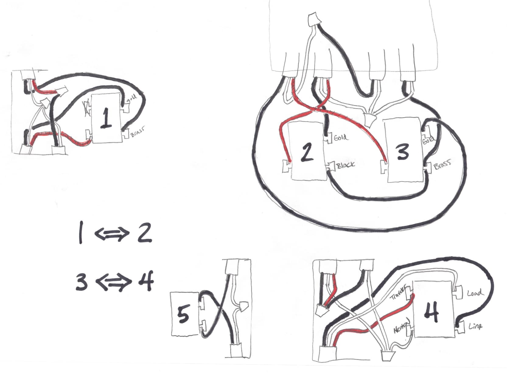
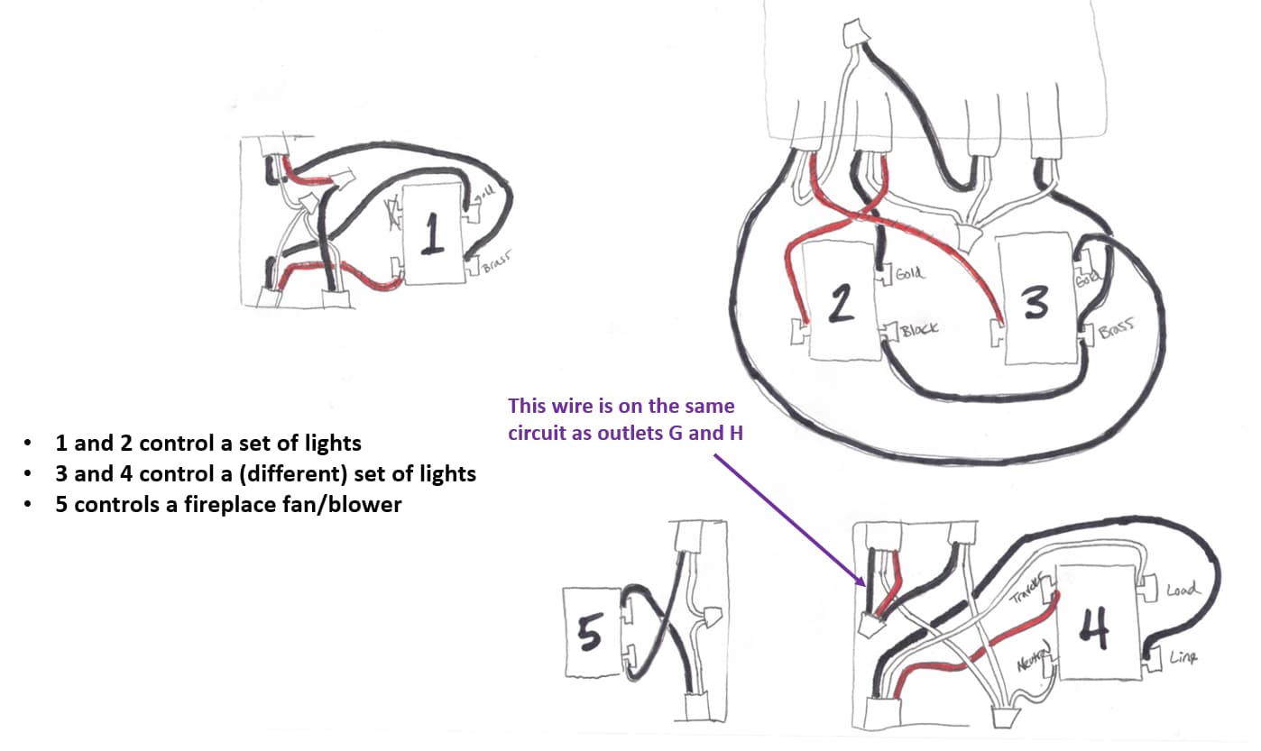
Only part way through this. I’m through the 1 <-> 2 switches. Agree with @harjms that the Line is the top right most adjacent to S3. The hot is pigtailed to S2 and goes out to S1 on the 3-wire. At S1, the 3-wire from S2 is at the bottom left.
At this point, it appears the feed to the lights goes in two directions. Not sure why you’d do it with a 3-wire though, although you could. So I’m thinking out via the 3-wire top left and then out via the 2-wire, bottom right.
Well I very much appreciate your guys help on this. I may have to hit the sack for tonight, and can resume in the morning. Since I can’t track down the still-on circuit in breaker 4 just yet - is it safest to completely disconnect the red series, so as not to induce accidental damage to it? I’m just worried about leaving half a switch box hot overnight, with half the wires removed.
Yea no worries. You can disconnect the red if you’d like. I would just cap the hot wires in where sw 4 is at with a wire nut to prevent accidental shock or touching. Don’t cap the BLK and white together. Use separate wire nuts.
Morning all. Would it help if I inspected the outlets that sit below these switch boxes, and add them to the diagram? Since they seem to be on the same circuit?
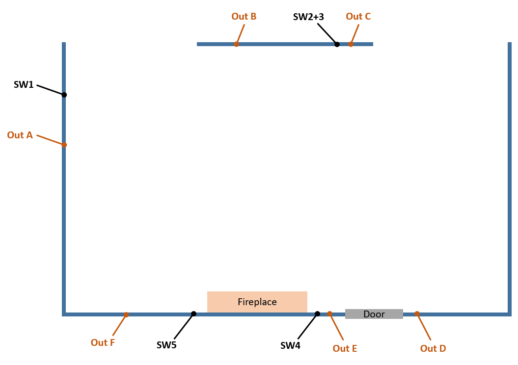
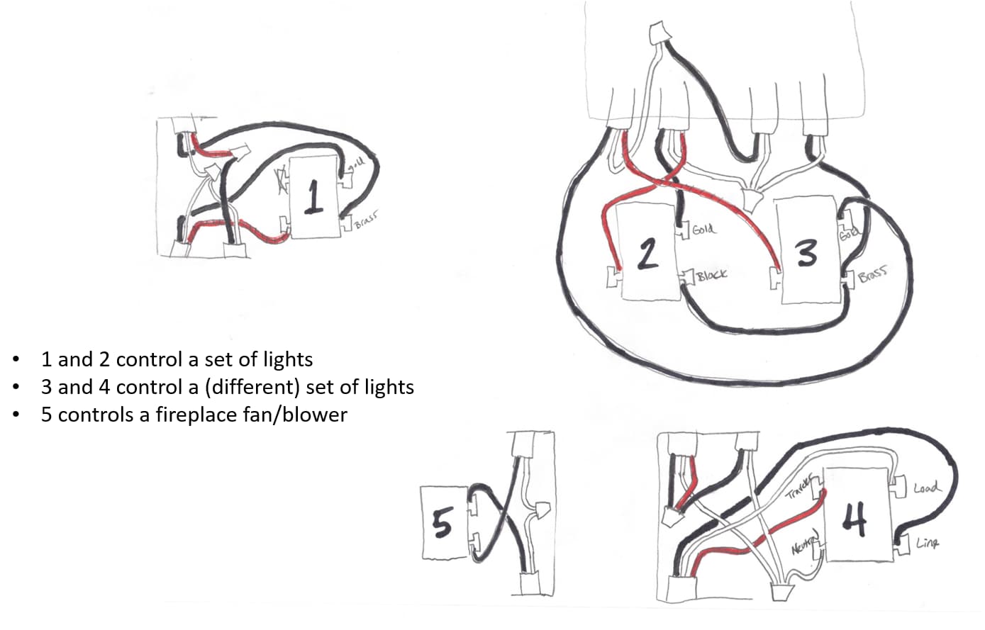
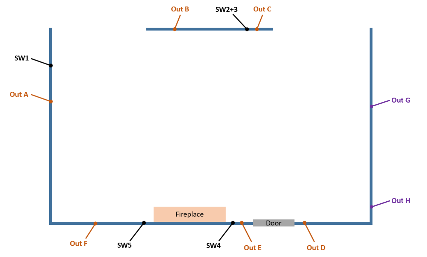
So I haven’t cracked into the outlets yet (there are 6 of them that seem attached/tied to the ceiling light circuit - so not sure which one to start with). But I realized there is a 5th switch in this room that seems to be on the same circuit as the lights - but it doesn’t control the lights. It’s next to our fireplace, and controls some sort of blower/fan that is embedded in the brick hearth behind a mesh plate (we’ve never used our fireplace, haha). I’ve added it to my diagram as switch 5. Does that help uncover anything?
Fifth switch probably does control the fan/blower under the fireplace. Usually, there’s a thermal fan switch in line that is mounted via magnet on the bottom of the fireplace. Once it gets up to temperature, it’ll activate the blower (assuming the switch, in your case, sw 5) is on. most likely unrelated, unless the upper right 14-2 in the box w/ sw 4 goes to it or lower right 14-2 in box sw 1.
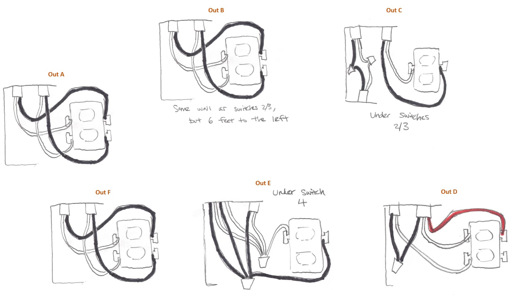
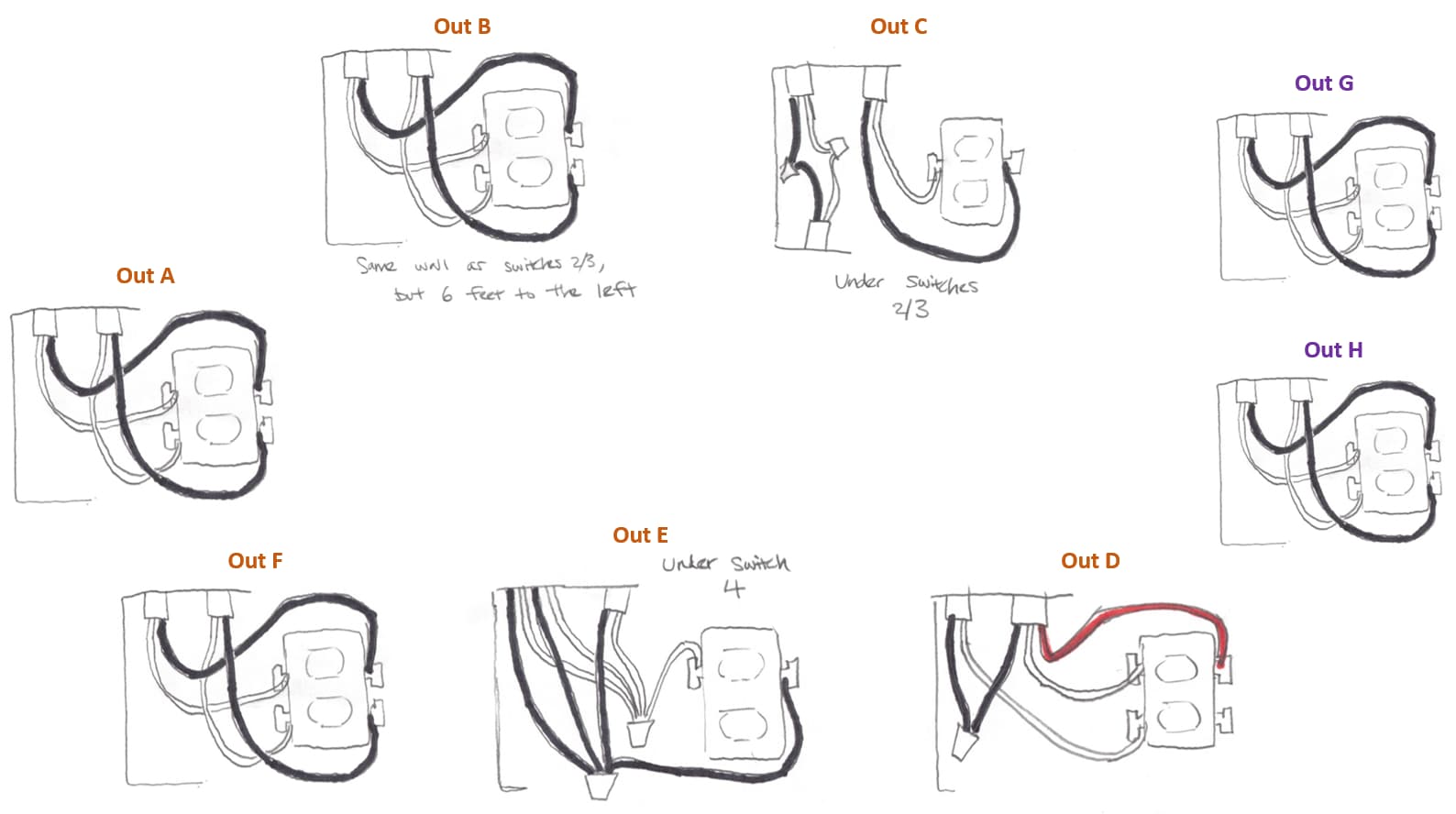
I see. So should I start drawing up all 6 outlets next? There is one below sw1, two on the wall below sw2/3, and 2 on the wall near sw4. If you think there is a good outlet to start investigating (over the others), just let me know.
I would focus on the ones directly near the switches. As you stated before, there may have been switched outlets for floor lamps. I mainly would like to see which wires are in those outlets. the 14-3 may connect to the outlets for the old switch circuit, and instead of installing new receptacle, they just tied the red to the hot to make both ports work on the outlet.
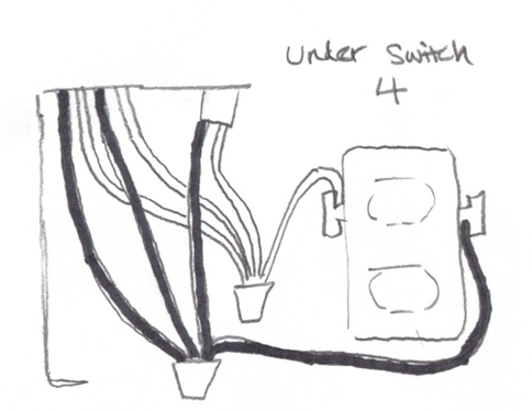
Ok, I first checked the outlet directly under switch 4. The top left has 4 wires (2 white, 2 black) and 2 grounds coming in through a single hole. I imagine it’s two 14-2s that just have their sleeves not reaching into the box?
As far as I’m aware, the switch that was there before the red dimmer was a dumb switch (with no dimmer). So I thought it was just a 3 way with switch 3 (which is a dumb switch with a dimmer tab on it). Those two switches controlled the same ceiling lights. But before we lived here, it seems those switches controlled outlets, because the ceiling lights were an addition just before we bought the house.
Ok, so there were two other outlets that were on a different breaker. I’ve labeled them Outlets G and H. It turns out that the “hot” black wire inside switch 4 (that stays hot when the ceiling light breaker is shut off), is on the same breaker as outlets G and H.
So switches 1 through 5 (except for the one marked wire in switch 4) and outlets A through F, and the two sets of ceiling lights are all on one breaker. And then outlets G and H, and the marked wire in switch 4 are on another breaker.
Gotcha. I was really hoping to have switch 4 be a Blue, so that it could have an LED strip (I’d program it to give status to the garage door - since the switch is right next to the door that leads into the garage).
My initial hope was Blues on 1 and 4, and Whites/Aux’s on 2 and 3. I assume that forces me to non-neutral on the 3/4 light circuit, right? If so, I say bring it on.