I’d eventually like to install a couple of Inovelli Red Dimmers in my living room. The house we’re in was built in 1969. I popped off the panel for the two light switches (one for the living room light, the other for the front porch light) to see what things looked like.
I assume the black and white are the load and line. Also, given the age of the house, I didn’t expect to see any neutral wires. My question is concerning the copper ground.
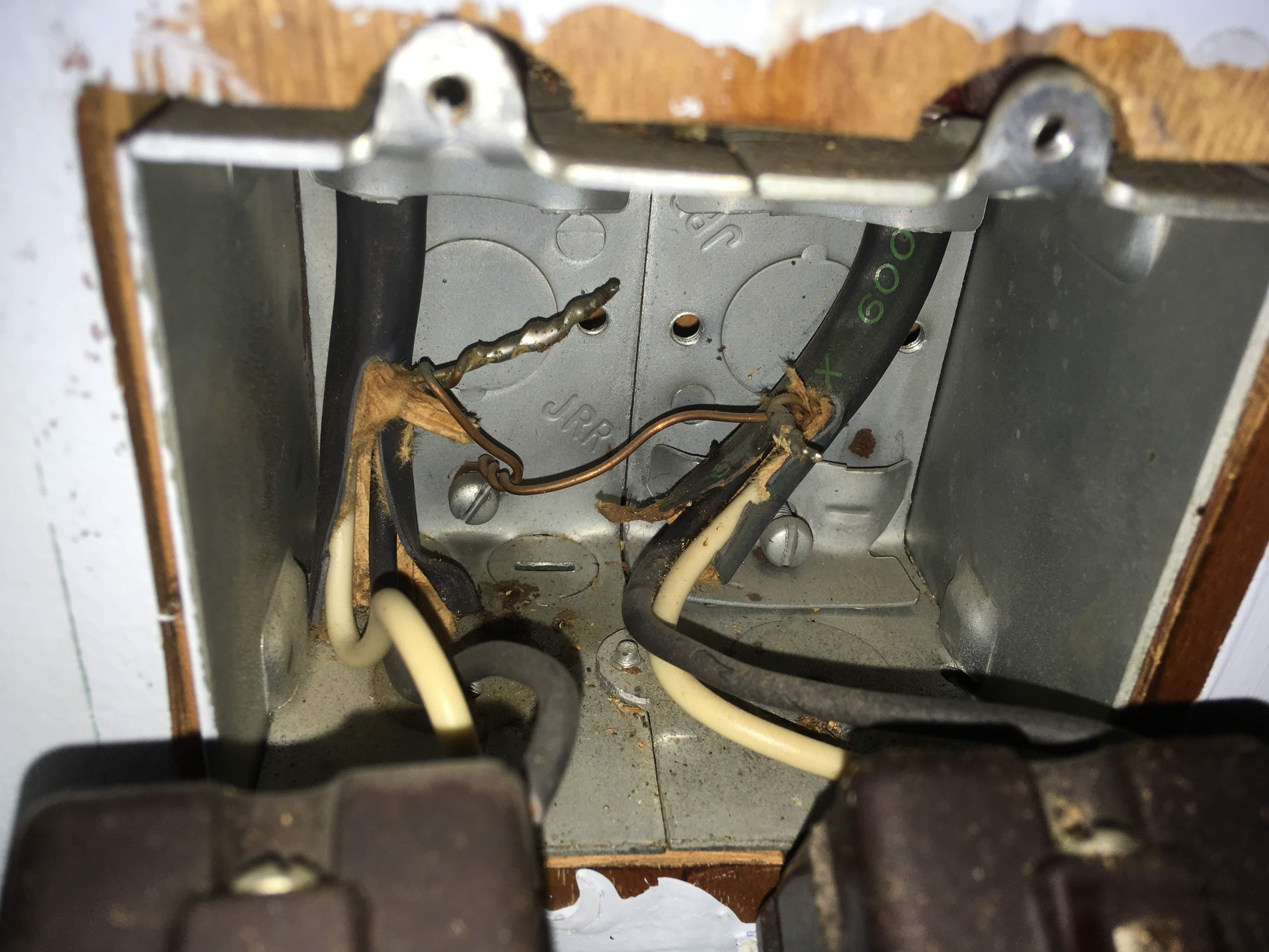
The copper coming from each line appears to be soldered to another piece of copper, and then screwed into the metal housing. So, am I correct to assume that since the housing is theoretically grounded, they just used a “jumper” piece of copper, which soldered to the ground wire, and connected it to the housing?
IF that’s the case, could I get two more short pieces of ground wire to “jumper” between the Inovelli switches, connecting them to the soldered portions with a wire nut?
Correct. You can use a couple of bare 14ga copper wire and wire nut to the soldered area (first for me to see) or use a new pig tail from a screw on the box. I’m just glad to see the box is grounded too. More times than not, it’s not grounded. @bry - Any NEC issues with the above recommendation? Wasn’t sure if utilizing the soldered area…
I’ve never seen the soldered twist before either, but nothing wrong with that. I would just make pigtails with 2 grounds for the the two switches. Twist them over the existing ground and cap with a wire nut, probably a larger one, red perhaps. No need for the additional grounds to be directly connected to the screw in the box. Use a pair of lineman’s pliers or similar if possible, and make sure you get a good binding twist.
You don’t see grounds going to the switches because the box is grounded and the switches are bonded to the box. I’d still ground the Inovellis in an abundance of caution.