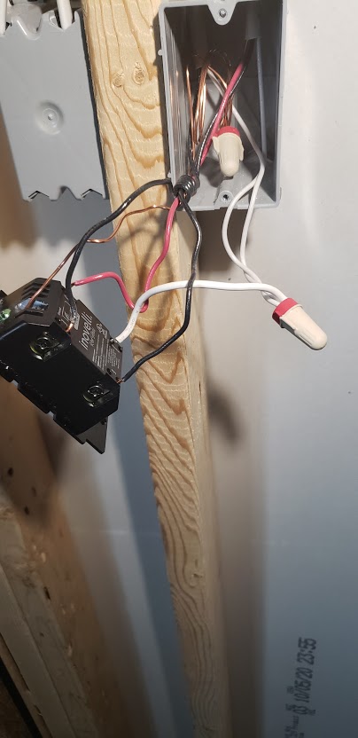
Brand new construction. Appears to be Line/Load in Separate Boxes (Neutral Wire Setup).
The dumb switch appears to disable the LZW30-SN when it is turned off. If the dumb switch is on, then the LZW30-SN works as expected.
I’ve swapped the switches and boxes and checked my wires to ensure I didn’t swap out the common. I’ve even put the original dumb configuration back together, tested, and started from scratch. I can’t figure out how to get the smart switch to work when the dumb paddle has been used to turn the lights off.
How did you determine what box the Line was in? It sounds more like trial and error as opposed to testing since you said you swapped the switches.
I THINK that you have a line in one box and a load in the other based on what i THINK are a 2-wire and 3-wiore in each box.
Can you post higher resolution pictures? When you zoom in on yours to trace the wires, they become pixelated. It’s tough to see what’s going on with that resolution:
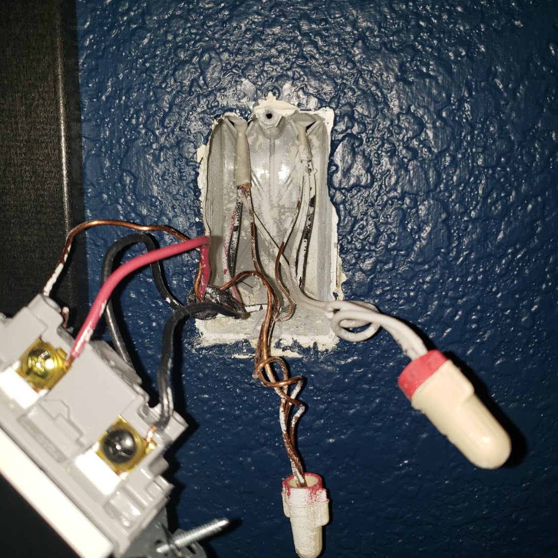
You are correct, it has been a bit of a grue hunt. You are also correct that I have 3-wire and 2-wire in each box. Hopefully these pictures will work better.
I have 9 more 3 way circuits to do, so any suggestions on identifying the correct box for line. In this particular circuit and in a perfect world, I would like to have the smart switch in the box on the blue wall and the dumb switch on the unfinished wall.
Ok, thanks. My understanding is that Grue hunts are usually hopeless endeavors, so let’s hope that’s not the case here. I’m thinking the scientific approach is more appropriate.
So when you have a 2-wire and 3-wire in each box, that suggests that the Line and Load are in separate boxes. You will have the Line coming in via one 2-wire and the 3-wire in the same box goes to the other switch. At the other box the 3-wire is coming from the other switch, and the 2-wire is going to the light.
So you need to figure out which one of the 2-wires is the Line. To do that, USING A METER, disconnect the 2-wire from anything it’s attached to and test between the white and the black. You are looking for the one that gives you 120VAC more or less. That 2-wire will be your line. You can then go do the same thing for the other 2-wire if the first one you test isn’t hot.
Start with the box the dumb switch is presently in. Let’s figure out where the Line is and then go from there.
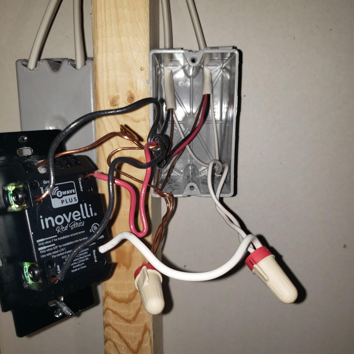
Question: In the box where the Inovelli is presently, which black conductor is coiled around the rest, from the 2-wire or the 3-wire?
Ok, that makes sense. Some electricians will wind the common around the other conductors. In that box, the common is the black of the 2-wire that goes to the light. That’s why I suggested you test the other box first.
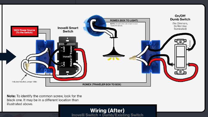
So the Inovelli should go into that box with the Line, where the dumb switch is now. You’ll use the following diagram:
When you use the backwire holes on the Inovelli, trim the bare copper end to that no bare copper is exposed outside of the switch. That way, when you tuck it back into the box, a hot conductor won’t accidentally come into contact with a bare ground.
Thank you very kindly, sir. This is exactly the type of assistance I was seeking. Direct and with clear explanations. Thank God I don’t have any 4 ways!