Box 1 (where the load is) has a red, and two blacks. One is line one is load.
Box 2 just has the red, and two blacks as well.
When using a multi-meter,
Box 1 is as follows:
Switch down position:
Black screw – always hot
Bronze screw --13v in switch down position – light is on
Switch up position:
Black screw – always hot
Bronze screw 120V
Light is off
Box 2 (while switch is in down position)
Black screw – 120v
Bronze – 13v
Light is on
The romex bundle with the red wire is connected to the bronze screw (also a neutral in the bunch)
The romex bundle with just a black and a neutral is connected to the black screw.
Obviously the LZW31 will lose power when Box 1 is turned off. When it is turned on, the LZW31 will turn the light on and off normally.
Can anyone please assist? I have been able to do all of the other switches in the house with no issues!
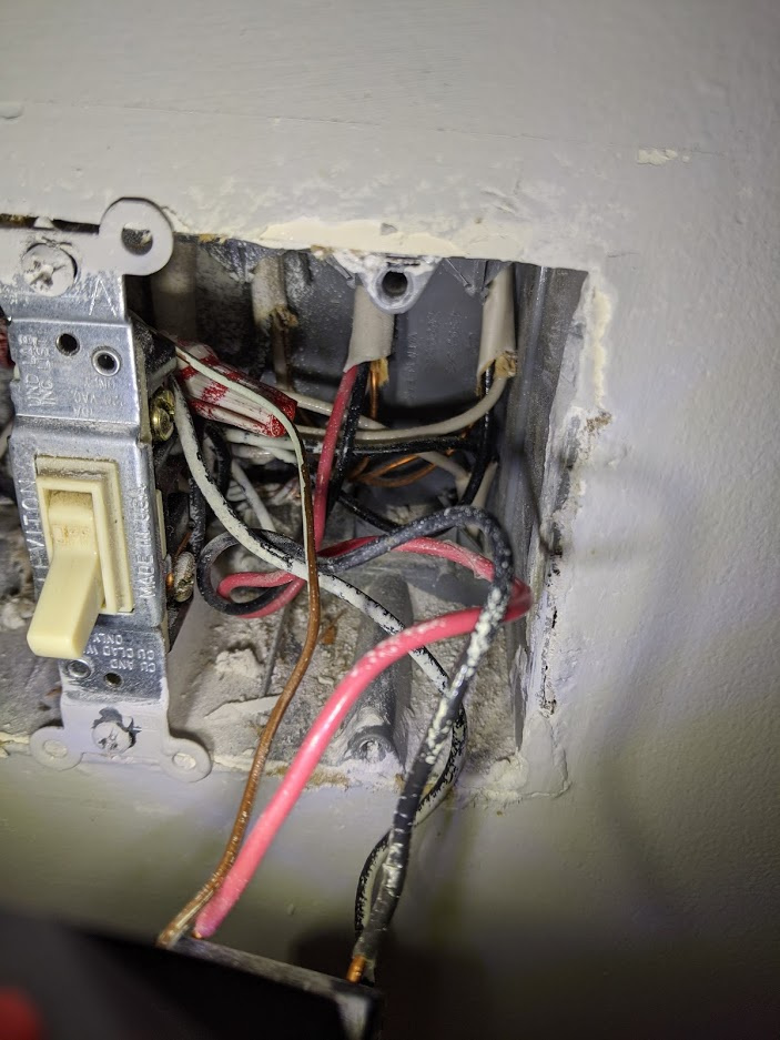
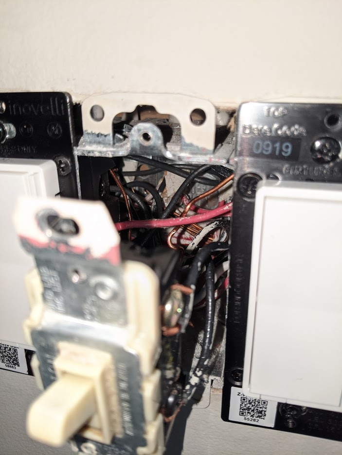
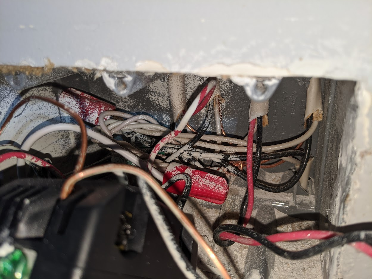
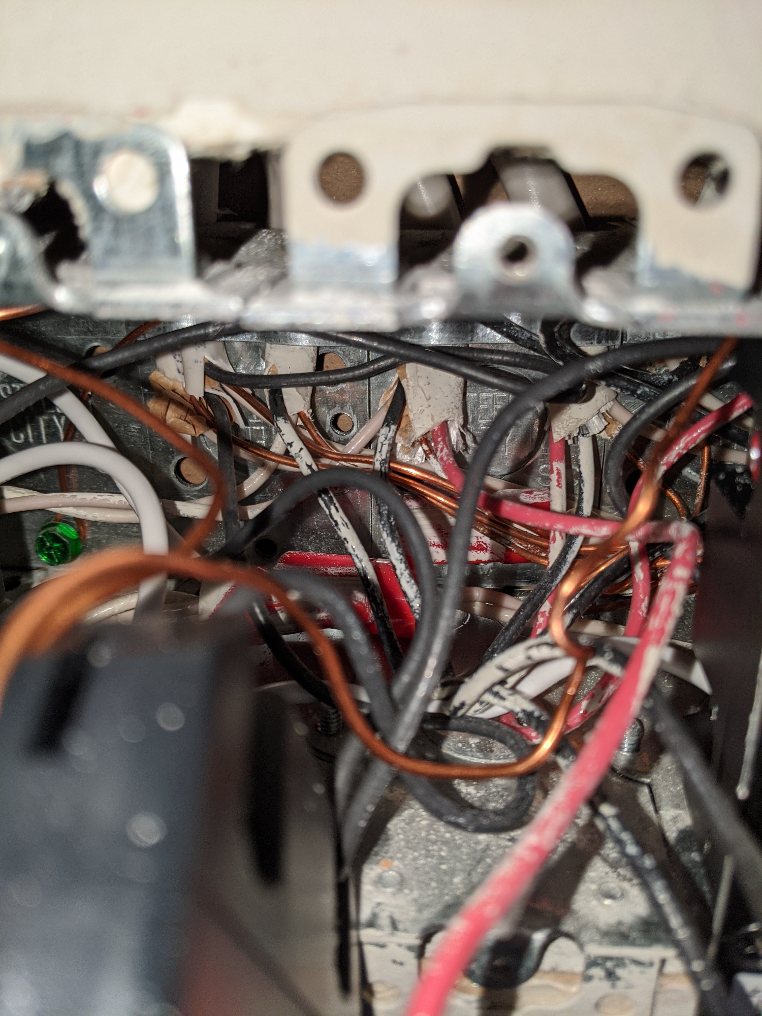
Can you post pictures of both boxes with the dumb switches that are working connected? Enough pictures that we can see the connections to the switches and inside of the boxes clearly. Pull everything out as far as you can.
I appreciate the fact that you took the time to write up your findings, but it is a little bit tough to diagnose with a description like that.
We’re going to do this in stages with you double-checking a couple things. It’s not that I disagree with what you posted, but I have to work through this methodically.
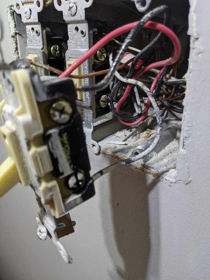
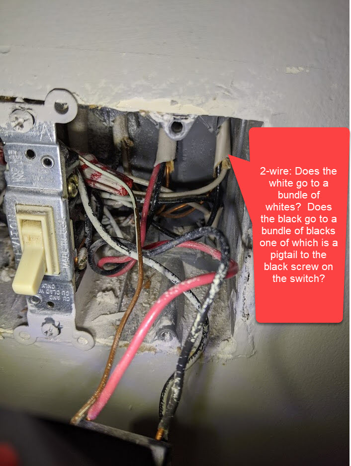
Let’s start with the 2-wire Romex coming in the top right of Box 1 (see the pic below). You may need to temporarily pull the switches to the left out to get at what is back there. Answer the following pertaining to the 2-wire:
1 - Does the white go to a bundle of whites?
2 - Does the black go to a bundle of blacks one of which is a pigtail to the black screw on the switch?
Then . . .
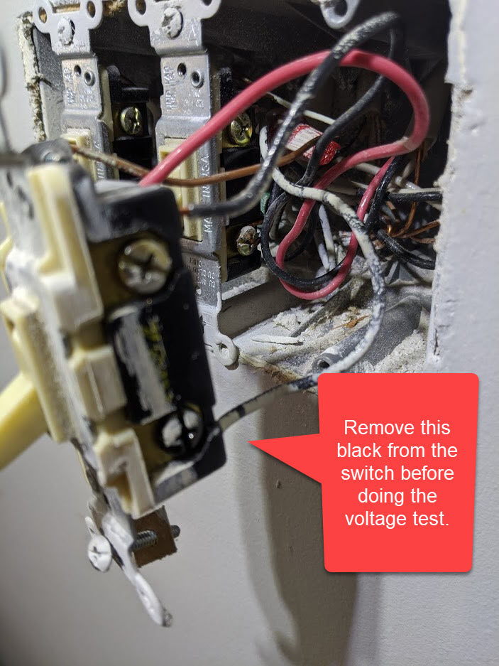
Remove the black wire attached to the black screw on the 3-way switch. With the wire removed, use a meter to test between that disconnected wire and the neutral bundle, which should be the bundle where that white from the 2-wire discussed above is going. Just unscrew the cap off the white bundle temporarily. Do you get 120V? Test this with the other switch (Box 2) in BOTH postitions. I am guessing this will be constantly hot irrespective of the other switch’s position.
That’s great, but you need to make the measurement in Box 1. We’re not in Box 2 yet. Between the black wire on the black screw removed and the neutral bundle as I described above.
I know that you are calling the black hot, but I need to confirm it’s fed over the 2-wire WITH the white as neutral. The black being hot alone doesn’t really confirm anything, since you could have tested it against the ground.
Also confirm that the black wire attached to the black screw in Box 1 is attached to the black bundle with the 2-wire black that you traced.
Ok, great. So what I believe you have is a standard 3-way line in one box, load in the other box configuration.
To confirm, I need you to check a couple things in Box 2, as it’s a bit tough to trace the wires in your pics.
I suspect that in Box 2, there are 2 separate Romex that have SOME conductors connected to the 3-way switch:
3-wire Romex: Black and Red conductors connected to the BRASS screws on the switch. White conductor connected to a white bundle (or at least the white from the 2-wire related here).
2-wire Romex: Black conductor connected to the BLACK screw on the switch. White conductor connected to a white bundle (or at least the white from the 3-wire related here).
Please confirm those connections and we’ll be good to go.
Thats brass screwS, right? Black to one, Red to the other. Pretty sure that’s what you mean.
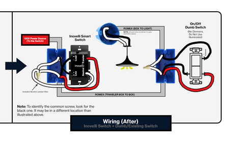
So this looks like a standard 3-way with line in Box 1 and Load in Box 2. The Inovelli will go in Box 1.
So your switch leg works like this: Power is fed to the switch in Box 1 via the 2-wire diagrammed above. The hot is attached to the black screw on the Box 1 switch. Power is switched via one or the other traveler (red and black on the 3-wire diagrammed above). The neutral is sent via the white on the three wire.
In Box 2, the switched hot arrives via the 3-wire (red or black travelers depending on Box 1 switch position) where they are connected to the brass screws. Depending on the Box 2 switch position, the hot is routed to the light via the black screw which is connected to the black on the 2-wire Romex. The neutral is sent to the light from the neutral bundle in Box 2.
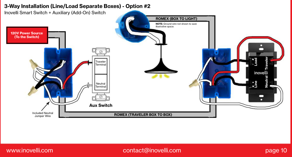
So the Inovelli goes in Box 1 and you can keep the dumb switch in Box 2. No rewiring of the switch in Box 2 is required.
In Box 1:
The black presently connected to the black screw goes to the Line on the Inovelli.
Pigtail a white conductor from the white neutral bundle to the Neutral on the Inovelli.
Black from the 3-wire to the Load on the Inovelli.
Red from the 3-wire to the Traveler on the Inovelli.
Leave the white from the 3-wire and the 2-wire alone.
It depends. Are you just looking for dimming in Box 2? Or the LED? The LED on your switch doesn’t provide notifications so it would just be the illumination level. An Aux switch would provide dimming.
Are the other switches in Box 2 on the same breaker as this leg? I believe you said the white from the 3-wire was tied to a neutral bundle, but please confirm.
Bry’s got a good handle on your problem and I don’ t want to steal his thunder. However since I’m here…
To install the Inovelli to box 2 you will need an Aux switch in box 1.
Very tangential question since I’m an addict now and currently tearing apart all of the three way switches I have to find out where the neutral wires are.
When you have an LZW31-SN installed in a three-way with a dumb switch, how does the system behave when the dumb switch is toggled? I’ve been unable to find a good answer in all of my searching. Is the dumb switch position reported to the hub?
The switch knows the other switch was turned off, and it kills the circuit to the light. The switch then reports to the hub that it is off. Pretty slick.
The only way to keep the dumb switch is to put the Inovelli in Box 1.
To dim in Box 2, you can either do it with an Aux in 2 and the Inovelli in 1, or we can turn it around and put the Aux in 1 and the Inovelli in 2. In either of these you’re going to have a dimmer/on-off in Box 1.
So the AUX switch essentially is just a switch that communicates with the hub to tell the Inovelli switch what to do, right? All done via the programming of the hub?