I have 10 lights in my basement all connected to one outlet. I want to make the room a smart room. I bought a red dimmer switch and I noticed that in my wiring, I have a black wire a white wire and a copper wire. Inovelli provided some excellent instructions for a wide variety of hookups, but I never found the one that mentions if you have a copper wire as your ground. How do I hook that up? Did I buy the wrong dimmer switch, I’m not an electrician so feel free to make fun of me. Thanks for the help
Are the lights really connected to an outlet? Or did you mean switch? I’m asking as if they really are plugged into an outlet, it’s not a good idea (and violates most codes) to connect a dimmer to a receptacle.
Assuming the lights are connected to a switch, is there only one 2-conductor Romex in the box? If there is only one 2-wire in the box, then you have a no-neutral configuration. The bottom of page 3 on the right describes your configuration.
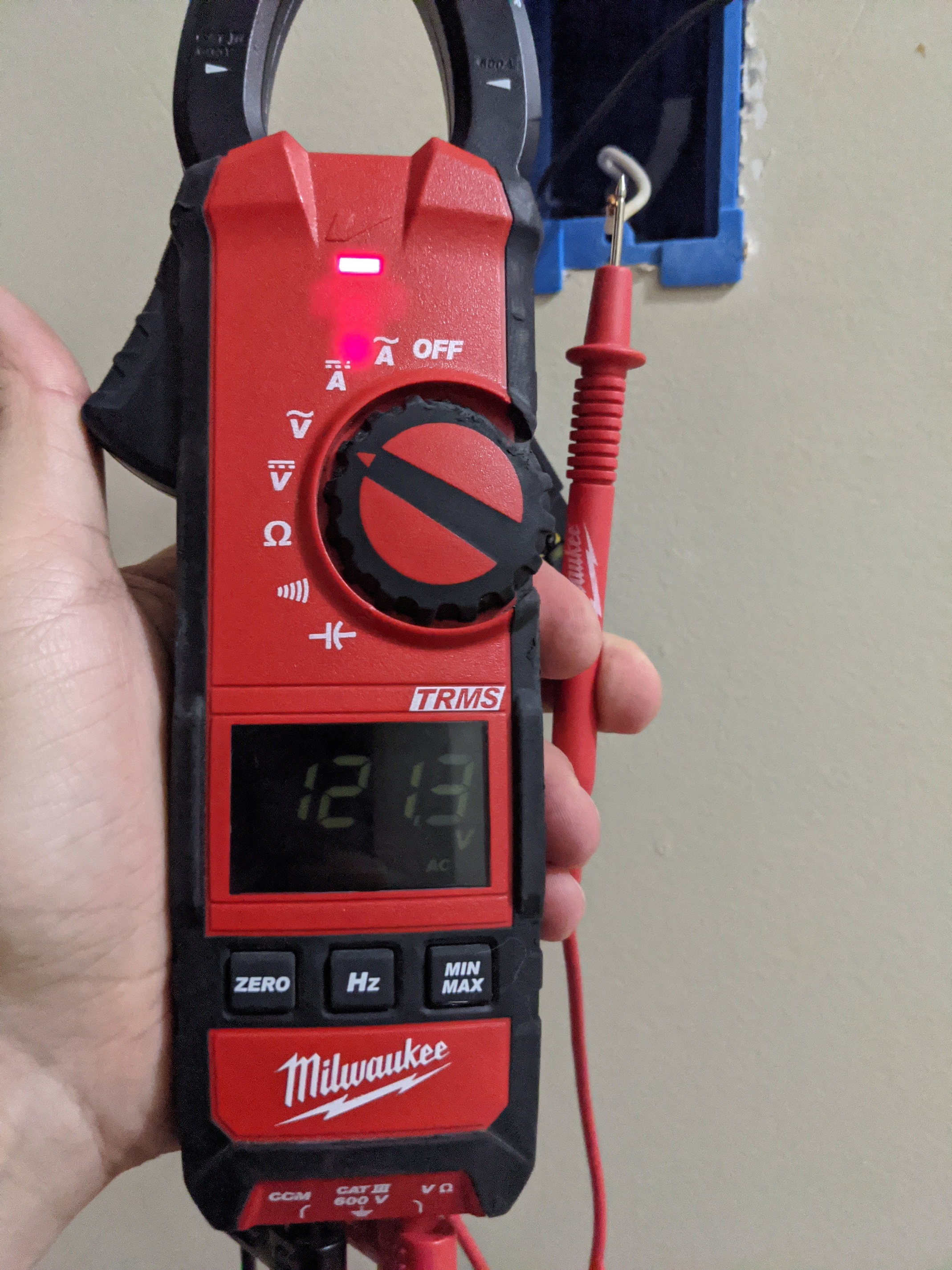
One of the two conductors in the box will be hot. You can test by using a meter with one probe on the ground and the other on the disconnected black or white. The hot goes to the Line terminal. The other one goes to the Load terminal.
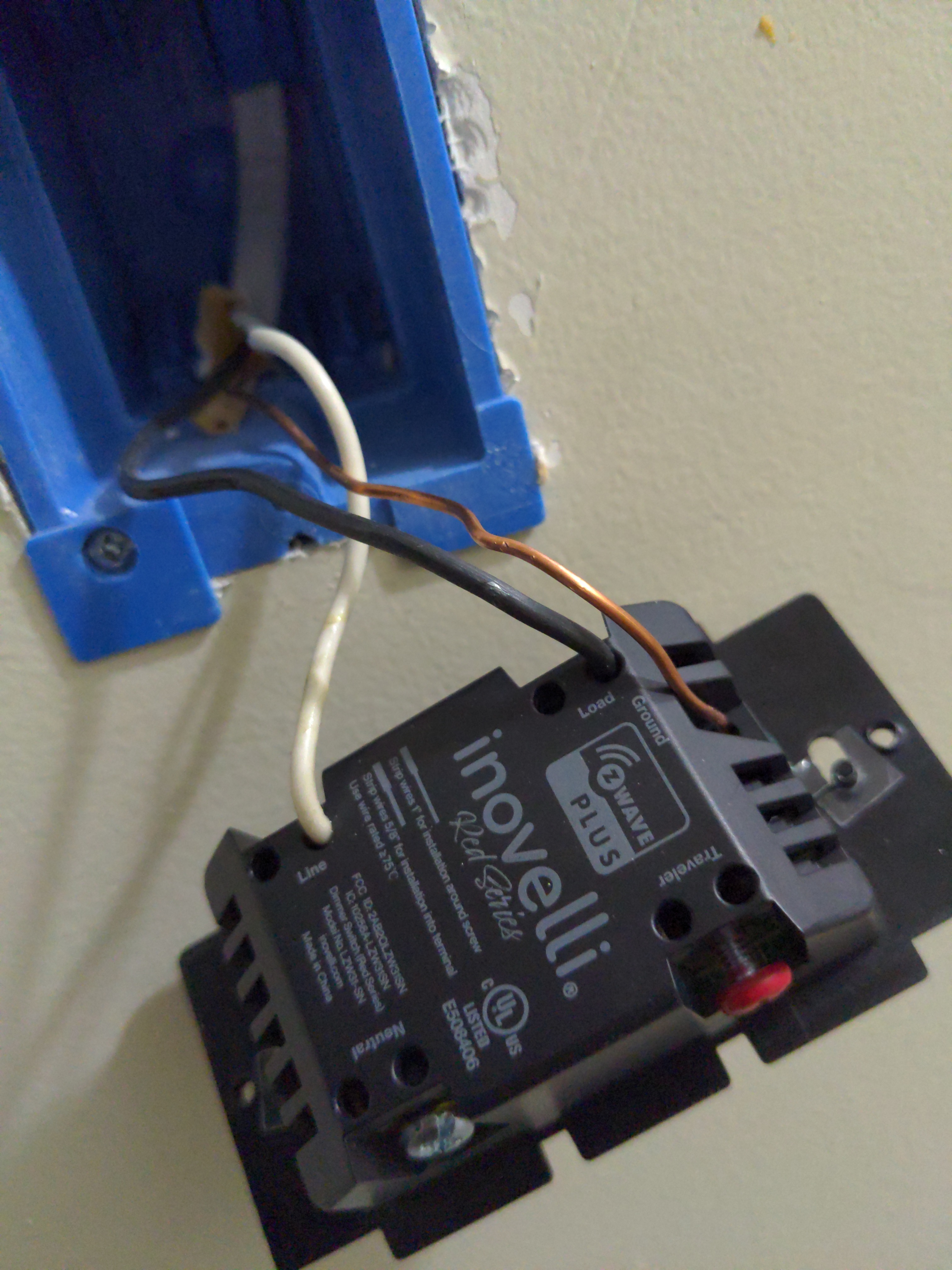
The bare copper is your ground. You should pigtail a bare copper and connect that to the ground (green) terminal on the dimmer. (Pull an 8" piece of bare copper from a piece of Romex.)
You will need a bypass installed at one of the lights.
It might not hurt to post pictures with the switch pulled out and a clear view of everything in the box.
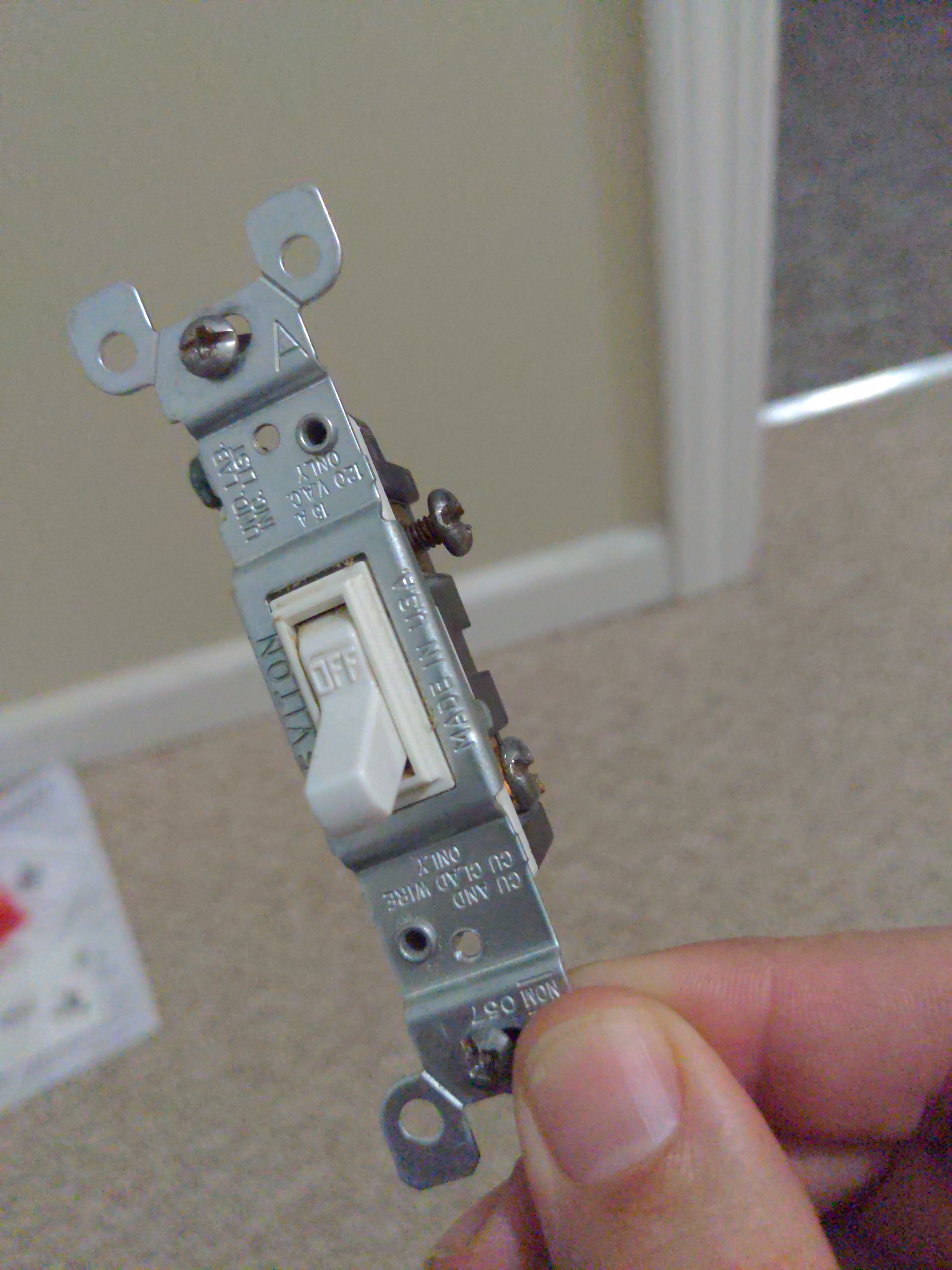
I have one wire coming out of the on/off switch outlet. It has three wires in it, black, white and copper. on the back of the dimmer switch there are four labels; line, load, neutral, traveler. Should I connect the copper wire neutral? I’m going to assume I connect the black wire to load and white wire to line.
This is correct but additional information might be helpful.
All Romex cables have a bare conductor that connects to the ground at the breaker panel. It is the “Safety Ground” it is connected to the green screw if each device, dimmer, switch, receptacle, light fixture housing etc
It is usually part of the metal body of a switch or receptacle or fixture.
It has nothing to do with the dimmer or switch function, it is there for safety and cannot be used in anything else.
Maybe. The Ground is correct. Did you test for which wire is hot as I described in my post above? You can’t go by color. Whichever is hot goes to the line,
I have the paper version of the attached PDF that’s in this thread. Am I missing something? Where in any of the diagrams do they describe wiring up the ground. Is that considered too basic to diagram out in the directions? I want to install more of these switches in my house. I’d like to do the single (one-way?) light switch replacement with the red dimmer switch.
The multimeter said the black wire is hot, I did not test while the breaker was off
Wiring diagrams may or may not show the ground. But it’s always the same. The ground is connected to the green ground screw. This is true for smart switches as well as dumb, mechanical switches.
In your situation, since the black wire is hot, you have your connections reversed. The hot goes to the Line terminal. The white goes to the load.
Did you install the bypass at one of the lights?
Are you saying I need to determine where the other end of the white wire (Romex cable) goes from the blue box and see how it’s connected?
Blockquote
Blockquote
No… I’m not sure. I haven’t done anything besides replace the on/off with the dimmer switch.
Is this something that would have been done regardless if it’s a smart home project or not? I guess what I’m asking is how do I determine if the bypass has already been done or not.
Thanks for everyone’s help.
You need to determine which of the two wires in the switch box is constantly hot. The easiest way to do that would be by using a meter between each of the conductors and the ground. That hot goes to the line terminal.
Depending on the amount of wattage your bulbs are drawing, you may need to install a device known as a bypass at one of the lights. You would know if a bypass was installed as you would have installed it. This is required for the switch to work properly in certain non-neutral situations.
I would recommend that you consult with a licensed electrician to assist you with this project.
1 Like
Yes,
Based on this thread and my basic understanding of getting shocked, I contacted our electrician here at work. When I mentioned there was just a single Romex cable and not two coming out of the wall box, his eyes got real big and he said, “That’s not to code”
When I get home, will investigate how the on/off switch was wired. Parts of my base ceiling are drop down tiles and easily removable. Stay tuned for more pictures.
If you are referring to the safety ground then it is not addressed in the wiring guide I’ve read.
That could be because it isn’t functional, it should already be on the switch you are replacing and it sometimes is not an extra wire. Some older buildings use metal jacketed wire with metal junction boxes. In these cases the safety ground is the metal jacket to the box to the switch via the mounting screws.
I agree though, it wouldn’t hurt to have some additional wording in the wiring instructions.
1 Like
I think we are getting lost in the weeds here.
Your description above will work fine. In this case it does not matter if you reverse the line and load wires, AC current has no polarity. So you don’t need to pull the ceiling panels and dig around up there.
However be careful, reversal in any 3-Way installation will not function correctly.
Also:
- verify the 10 lights do not exceed the dimmer capability
- Set Parameter 21 to 0 (no neutral, the default is 1)
- Set Parameter 22 to 0 ( single pole, the default is 0)
Sometimes these parameters don’t “take” on the first try so if something is not working correctly you should repeat setting these parameters.
I would be curious to know why your electrician believes this installation is not to code. I know some of the newer codes require a neutral in every box, most homes were built before this was the case so are considered to meet the code that was in force when the building was built.
John
1 Like
Just guessing, but I’m thinking he saw that was an old-work box, meaning that box wasn’t installed when the sheetrock was. So more than likely, that wiring run was installed after the house was built. Plus since the electrician knows the OP, he may very well know the age of the OP’s house.
While local codes may vary, the NEC starting requiring neutrals in the boxes in the 2011 code. Anything before is grandfathered in, obviously. But if that box was installed after 2011 and subject to the NEC 2011 code, then it should have had a neutral in the box.
Blockquote
Bry,
I want to point out I made a mistake earlier. I said the black wire was hot. It is not, is the white wire that is hot.
Bry,
Thanks, I didn’t know when the code went into effect. Also I’m sure you remember a few folks back where the installer used the line in one box and a neutral from another…things happen.
The house is built in 1991. He’s only going by what i told him, so it might be me. I think he was just going by there being just the one Romex cable from wall box.
A single Romex to the box was a common way to wire switches. That’s why there are all sorts of questions about non-neutral configurations.
We can’t know what the NEC folks were thinking with the new neutral requirement but I wouldn’t be surprised if it was at least partly for home automation.