Basically what @Bry said, with a bit of additional information gleaned from the photos…
While it is always best to use a tester to determine which wires are which, the fact that the cables have different color sheathing helps out a bit…
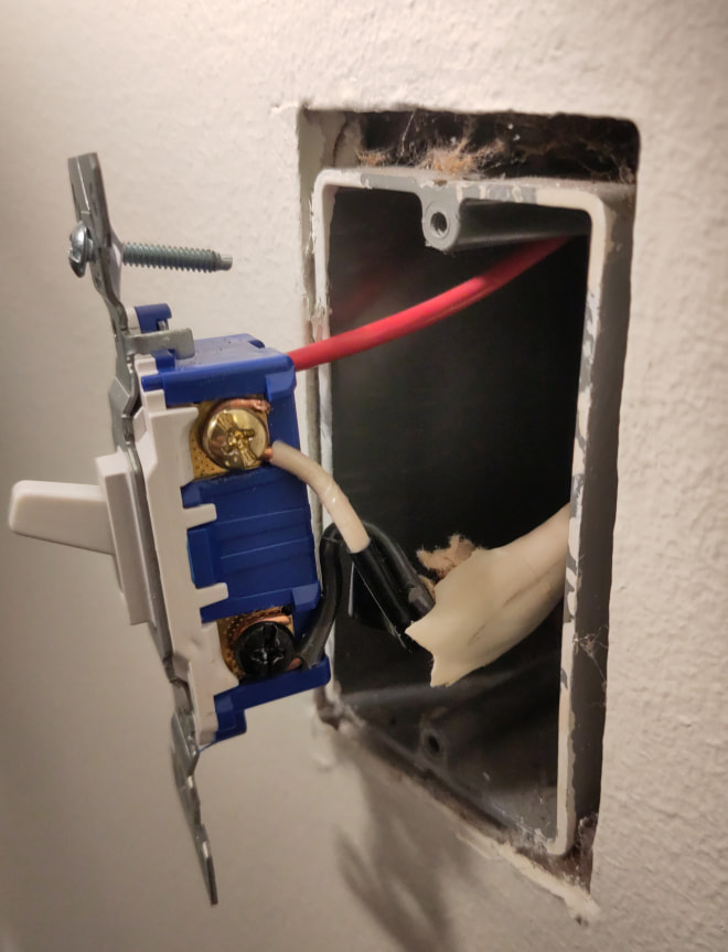
Switch 1 - The black wire is your Line, red and white are currently your travelers. This can be determined via the cable sheathing being “white” instead of black. In the ceiling box, power comes in on the left most cable and that black connects to the black in the “white” cable. That white wire that comes in with the power and connected to your light should not have that black tape on it marking it as a live wire as it is a neutral.
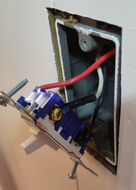
Switch 2 - The black wire is your Load, red and white are currently your travelers. This is determined via the cable sheathing being black. In the ceiling box, the black wire from the black cable connects to the light. The two white wires connected together between the “white” and black cables DO need to be marked with black tape as they currently are as they are NOT being used as neutral wires.
The red wire seems to go directly from box to box… while not code, there’s nothing an electrician like me on the other end of the internet can do about it. If you absolutely had to make it right, you will need to rerun the wiring for that circuit.
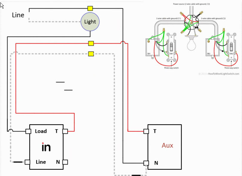
As @Bry mentioned, you will need to hook this up in a non-neutral configuration requiring an Aux switch. Due to this you will need to install the Dimmer at the Switch 2 location.
At Switch 1, you will connect the black and white wires together, as this will be the Line for the Aux switch, with the red for the Traveler. Because of this being a no-neutral hookup, the Aux switch will connect to Line (in place of the Neutral) and Traveler. I recommend adding a black pigtail to the connection of black and white wires so there is a single wire going to the switch instead of 2 to the same terminal. (as diagramed by @Bry in the post above)
At Switch 2, the white wire will now be your Line for the Dimmer, the red will be your Traveler, and the black will be your Load wire. Nothing will connect to the neutral terminal. (as diagramed by @Bry in the post above)
Note: Depending on the power draw of your lights, you may end up needing a bypass to help power the switch, especially with an Aux switch in there as well. This would connect the same as your light, to the switched hot and the neutral, in the ceiling box.