As @EricM_Inovelli suggested, I changed my dim rate 1 to one. I still have dimming over a period and the stepping no longer shows.
@Bry does that work when you dim by hand? I have very smooth dimming via z-wave, but really choppy dimming from the paddle using a rate of 1 on each.
Yes, I’ve set both to 1 and I do not see any jerkiness using the switch. FWIW, this is with CFLs.
@Bry I wonder if there is a slower response in the CFLs (I’m on LED bulbs) smoothing it out. I’m trying to figure out a way to record it and trigger the event at the same time to show you what it looks like on my end. I’ve got ramp rates and dimmer speeds all set to 1, but really see a difference between the paddle and a z-wave command.
edit: I love that my solution involves setting up a spare ZigBee button and a special rule set just to test this out. Something very satisfying about having to engineer something just to record a video of the behavior. I know I’m preaching to the choir, but it makes me feel extra geeky… in a good way.
edit2: Well that didn’t work out. It’s probably “jumping” between 30 and 60Hz and doesn’t show on my video. At a dim rate of 1 it’s also way too fast to get the brightness right by hand. My usual default is 3 just to get some measure of control.
Here is my theory:
Lets assume the dimmer can handle 100 distinct levels of brightness, and you have a dimming duration set to 4 seconds. This calculates out to 25 levels per second when going from 100% brightness to 0% brightness. 25 levels per second is about the same as some movie frame rates, so there is a chance this is imperceptible to most humans.
When using the paddles to change the dimming level, the brightness levels change at the fixed 25 levels/sec (based on a dimming duration of 4). Going from 25% to 0% brightness takes 1 second, going from 25% to 75% takes 2 seconds, etc. So far, so good.
If you set the dimming speed to a higher value, such as 10, you start to see the stepping effect. This is because it is changing brightness at only 10 levels/sec (100 levels / 4 seconds = 25 levels/sec).
You really start noticing this problem when you dim the lights via zwave. This is because when you send a brightness level to the device, your hub also specifies a duration for the change to take effect. Instead of dimming at a fixed rate of 25 levels/sec, it dims with a fixed duration. Going from 25% to 0% takes 4 seconds (6.25 levels/sec), and going from 25% to 75% also takes 4 seconds (but at 12.5 levels/sec). The smaller the change, the more noticeable the effect.
A possible solution could be to send a duration value that is calculated based on the amount of change. I am not sure if/which hubs allow you to do this, but something like the following formula could work:
INT(ABS(([OLD_VALUE] - [NEW_VALUE]) / 25))
This would essentially convert the duration to a fixed level/sec, and potentially eliminate the flickering effect.
That’s basically where I was heading, but I would strongly suspect implementation would require a firmware change or even a hardware change. Due to my particular LED bulbs, I only have 40 discrete levels between min and max brightness (despite going from level 1-99), so I think the issue is compounding. At a 4 second duration from min to max, I wouldn’t be surprised to find out I was only getting 10 stepped changes per second. I might try recording at a high FPS to see if I can count steps.
I really don’t see a reason why it should stop at brightness integer values in between ticks unless the processor in the switch is running out of cycles or there is a hardware limitation. It would be much nicer if the switch would interpolate and adjust the control voltage on the mosfet as many times as it could (like you are suggesting), but depending on how they are creating the control voltage it might not be possible. If they are using a lower clock speed PWM to fake it, they could be limited on the number of analog voltages the hardware can actually create, but I’m no electrical engineer. I only know I ran into issues with that playing with PICs back in the day.
Again I’ll throw in my $0.02 to this conversation because I’m a lighting professional and I have designed both AC lamp dimmers (phase control) and PWM LED dimmers. I hold a patent on one of the latter and at my day job deal with all sorts of dimming challenges, artifacts, etc.
What I really want to see from Inovelli’s dimmers going forward (besides interactive features, connectivity, 700 series ZWave LR support, etc.) is a great improvement to the dimming itself as I think many of us on this thread would agree. Having done the work both designing the electronics and programming the firmware I understand that there is one primary choice to be made when it comes to designing an AC lamp dimmer that propels most of the other engineering decisions and that is leading edge vs trailing edge phase control. With trailing edge phase control a dual MOSFET design is a requirement. For leading edge control a TRIAC typically is used.
120 times per second (in the US, it’s 100Hz in other parts of the world) when the AC waveform crosses zero, the switching device (TRIAC, dual MOSFET, or IGBT) is synchronized to either open or close based on whether it is trailing or leading edge. Typically leading edge control is easier to design with cheaper components while trailing edge control is more difficult to design with more costly components but superior in every other respect. If the Red Series dimmers are MOSFET and are indeed dual MOSFET as is typical of MOSFET AC lamp dimmers (one is needed for each direction of current flow) then it should be possible to implement with firmware (given enough CPU, RAM, flash, and other resources) a universal dimmer that can do either based on the type of load attached. Dimming an LED load with phase control generally is best with trailing edge operation so this would be high on my list for future Inovelli dimmers. Given how precisely the AC line has to be switched to achieve this without the dimmer self-destructing smoothness would be an easily achievable “by product” if not a key benefit on its own.
The second thing I would like to see improved is what I think @jtronicus and @fatherdoctor are advancing. I want some form of adjustable interpolation where I can decide just how much smoothing is desired (measured in milliseconds) and all calculations internal to the dimmer handled as 16 bit integer or 32 bit floating point math. It is easier to implement both during the same firmware effort as implementing one makes the other easier. 120 times per second (in the US, 100Hz in other parts of the world) the dimmer should update the duty cycle by varying the timings of the switching devices. This would lead to the smoothest possible dimming with no aliasing or artifacting since the dimmer would be updated every half AC cycle (the fastest possible on AC) and the math would be immune to rounding errors. Adding some additional smoothing just makes the occasional jump from mixed instructions from the Hub/button presses that much better. For example a 0 second sudden jump from 0% to 100% would still be just a bit smoother due to a 100ms or 200ms fade. This is particularly helpful for halogen filaments that are extremely short and therefore often too responsive to dimmer changes along with many LED bulbs.
@EricM_Inovelli/@Eric_Inovelli I can help with pseudo code and examples of any and all of the above if you would like. The big question in my mind is whether or not there is “room” in the 500 series based v2 dimmers for any of this or if this all has to go to a 700 series based future product (lots to be gained moving to ARM Cortex…)
Bonus points:
- “Bump” for LED bulbs so that when they dim up from 0% they get a brief instant of full power to charge their capacitors (we do tricks like this at work often)
- “Easing” such that the manner in which a dimmer arrives at its target value is additionally smoothed at the beginning and/or end of the fade
- Gamma correction for low wattage incandescent and LED bulbs to enhance the resolution at lower dimmer values (another common thing we use often at work)
7 Likes
Whoa, this makes too much sense why my Ilumin bulbs dimming via z-wave take forever from 1% to off vs when I switch them off it is instant.
Now I want to see if I can ratio the duration by the start/current percentage (0.75 x duration if starting at 75%) when sending the off commands… I don’t think ilumin has this capability, but I wonder if z-wave does for the switches…
As always, thanks for the detailed insight!
I forgot to mention one thing in my last post. There are certain bulbs that work better with the hardware in our Gen 2 dimmers. Since they are Mosfet & Leading Edge, there are certain bulbs that have a smoother transition than others. We have a list of compatible bulbs, but I am not sure if the compatibility requirements for the list are whether or not the bulb just works, or whether they perform optimally. Maybe @Eric_Inovelli can answer.
Compatible Bulbs for Inovelli Dimmer Switches Red and Black Series
2 Likes
I’ll second that statement. I’ve been through several bulbs and found many I can use with your Gen 2 dimmers that smoothly dim.
I would say that of any wish I would have of the gen 2 hardware (and looking forward to gen 3 hardware) it would be to eliminate the steepy-ness of the dimming using some combination of interpolation, higher precision math, and to adjust the algorithm such that the steps are no constant in time or size. There are many times when we want a longer/slower fade which should be free of steps or aliasing. That’s the use case. While at one second most fades are smooth there are many times when a five second fade would be better. If that five second fade is only a few percentage points of change the steps become really noticeable. For example fading from 61% down to 49% over 10 seconds when starting to watch a movie. This happens a lot with many LED bulbs that do not dim (visually) linearly.
@rpulivella Great write up! Since you are in the industry, and I was playing around in my tinker room, I was wounding if someone could take a look. Do these wave forms look correct to you and what you would expect to see for a dual mosfet? It’s been a couple of decades since my electrical engineering classes and I haven’t had a chance to bust out the scope in a while.
This was taken with an inovelli red dimmer switch and the earlier version of firmware. This was full power. What I don’t understand is why the scope was reading no clipping for the negative values. I think the break at the from of the wave form is the 85% = full on. I think this why the smart bulb parameter was introduced. This was taken with the switch in the off mode. I feel like I was still seeing some power leakage.
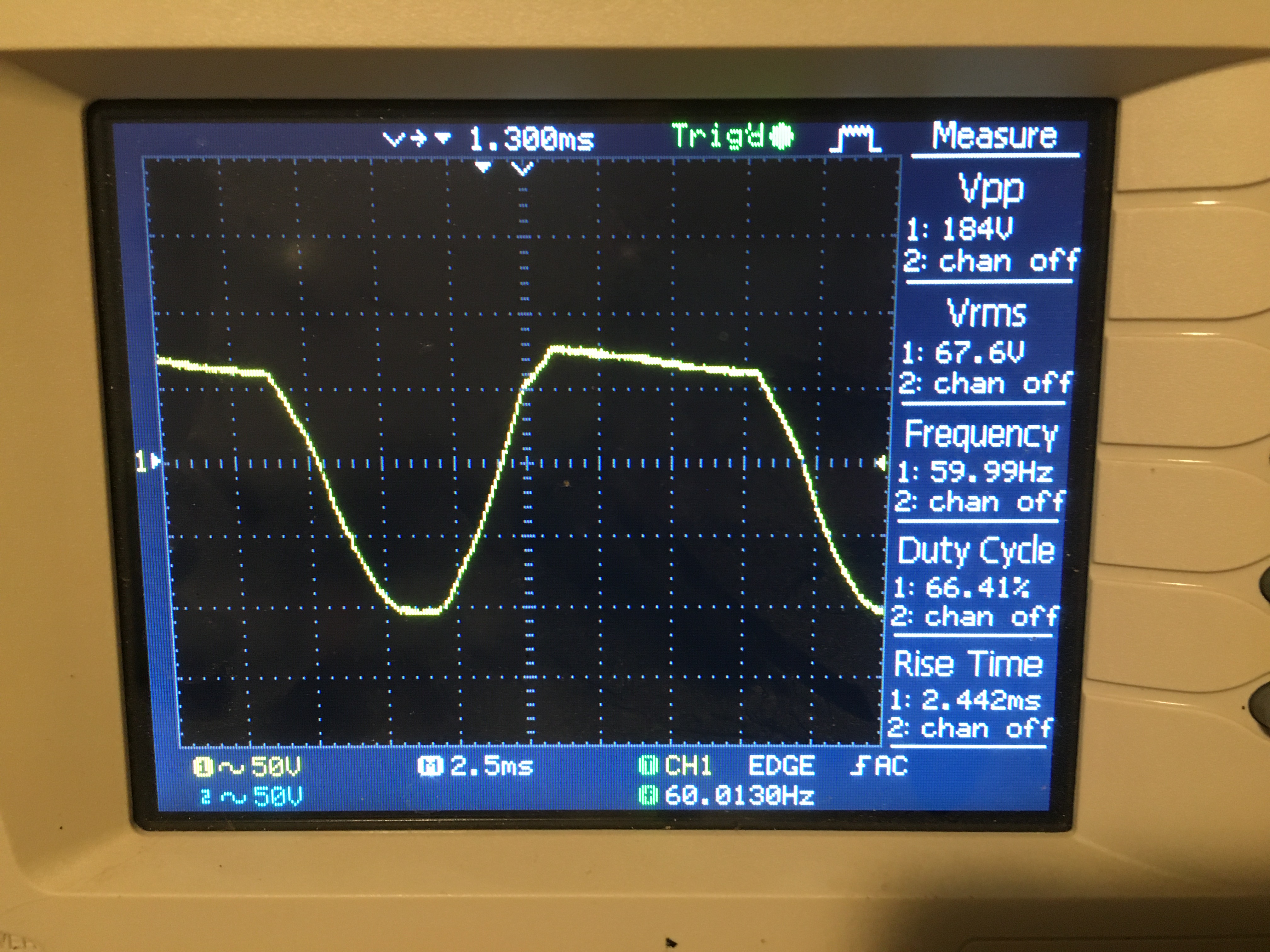
In both cases, I feel like it’s my equipment or lack of understanding on why I don’t see any clipping on the negative part of the wave but thoughts are welcome.
The switch was hooked up with a neutral and was powering a 60W incandescent bulb at the time. Ocillicscope was hooked up to the hot wire.
Thanks!
2 Likes
Just checking that you’re using differential probes and did not directly connect AC line voltages to your equipment. Doing so runs the risk of serious injury, destruction of your scope, and of course — erroneous readings.
Now on to your findings because this is exciting…
I did not design these dimmers but my hunch is that you are seeing only the positive side cut at “full” for two reasons:
- The dimmer has to steal some energy to power itself when operating in non-neutral mode. My expectation is that even if you wired your device under test for “three wire” operation with a line, neutral, and load connected then you might not have had the dimmer configured for “with neutral wire” power from the device page or other preferences/provisioning tool.
- Accurately timing the MOSFET (or any switch device) to perfectly align with the zero crossing requires either a secondary microcontroller, incredibly fast interrupt handling (aka ISR for those of you who have programmed using the Arduino libraries), a very low CPU load (unlikely knowing these dimmers are packed with features!) or some combination of these.
It is not possible from these waveforms to determine dual MOSFET vs TRIAC (or anything else) because it is leading edge. Trailing edge requires certain components whereas leading edge can be achieved using many topologies. I’ll leave it to @EricM_Inovelli to share what he and Inovelli feel comfortable sharing here.
That is a really strange waveform that would be impossible to produce using a simple MOSFET switch. It would have to be a high frequency switch and then filtered (or some other method). Again my hunch is this is related to the small amount of power required by the dimmer itself to operate. What you are seeing is the “cost” of that stolen energy. I also would add that if you did not use differential probes you should repeat your testing. That would rule out any sort of effects of the common reference (as opposed to differential).
Also: please proceed with extreme caution when measuring AC delivered from the wall — especially when using a scope without an isolating transformer, differential probes, and very sensitive overcurrent protection (and/or a ground fault interrupter). There is a serious risk to injury and damaged equipment. I have to say it any cannot encourage these safe practices enough. Such practices also lead to more reliable data so why not!?!
Oh and bravo @BuilderTroy as I’ve wanted to do tests like this on the Red Series for a while and also repeat the measurements using a low value resistor as a current sense to measure how an LED (capacitive) source actually behaves on these. But alas, the day job, all 16.5 hours of it yesterday, prevails…
Use DC coupling on the scope for the waveforms. Both waveforms have offset effects from the AC coupling.
It almost appears that the dimmer is only varying the positive half of the waveform, which doesn’t make sense. Half wave rectified would pass enough power to still light the bulb.
Oscilloscope was connected across the bulb, right? Ground lead to neutral and input to the hot wire?
If you’re up to it, we’d love to have your input for our upcoming launches. We’re working on the 5-Button switch as well as some ZigBee switches.
We do also have the ability to tweak firmware in the existing switches.
Edit: the more I’m reading, the more it feels like everyone in this thread could/should help. What do you think guys?
2 Likes
Count me in! 
1 Like
Not one of the original commenters, but I’m always in.
I was thinking about this and a few other things that frequently get discussed here. And this is more for @EricM_Inovelli to think about for the next generation of stuff. But it’s a possible answer to this question also.
Are you guys familiar with the Z-Uno? It’s a Z-Wave Arduino board, basically a little dev board with a bunch of GPIO pins and a Z-Wave radio. You define in software what command classes it exposes, and what they do, and it then can be included in the Z-Wave network.
That’s not the point though. The point is it’s a Z-Wave chip with two levels of code running on it. One is the base Arduino emulator that includes the ZDK and whatnot, the other is the user-provided Arduino sketch. The base code ensures it stays within Z-Wave specs no matter what the sketch says to do, and prevents a sketch from doing anything ‘bad’ on the Z-Wave side. Apparently both can be updated OTA.
I know from previous threads that Inovelli has considered open sourcing the switch firmware. So what I’m suggesting, is something like the Z-Uno- Inovelli writes a core code that handles the Z-Wave stuff, but then all the switch’s actual behaviors are dictated with a simpler, interpreted, user-editable script.
The switch would then ship with the base code and a userscript that accomplishes all the behaviors the switch does now. But that would be editable by the user.
Result would be if someone wanted a specific behavior- like let’s say they wanted their light to be at 0%, 50%, or 100% and never any other value, they could rip out the parts of that script that do the ramp dimming and replace them. Someone with a smart bulb could make a script that on initialization sets the load to 100%, then delete all the lines that sync the LED bar to the load. Someone with a unique setup could make the switch control one device and the LED bar represent something totally different. And the ramping could be tweaked far more easily to accommodate each bulb- for example if a bulb starts at 4% power, but is 50% bright at 20% power, and then gradually brightens the rest of the way, a customer could make a custom ramp for that bulb that would dim it up/down smoothly and evenly.
etc etc.
Basically, all the cool special use cases Inovelli is famous for supporting, and more, could be supported without Inovelli having to write code for every one of them. It’d take the Inovelli switch and put it customization wise much closer to a high end Crestron/Lutron product.
This is probably not possible with the 500 series chip due to space limits. But it’s something to consider for the next version.
1 Like
I could possibly help with some testing. I do have access to a Tek scope at work, 4-channel with isolated inputs to avoid the problems rpulivella posted about.
Awesome, I’ll create a group shortly (I’m putting it in my calendar to do early next week) and I’ll add the manufacturer to the mix so we can talk directly to their engineers/firmware developers.
Would you guys prefer to stick to Discourse (this forum) or MS Teams? We use Teams internally as it’s easier to IM the manufacturer, but I understand that can also be a hassle for some. Note: there’s only the project manager on Discourse and he’s basically a middle-man between us and their engineers.
I’m open to either!
Eric, I feel my expertise is outside this conversation btw. No need to add me.
That said, you never ceases to amaze me with your willingness to improve and improvise with your community.
I’m in…please let me know what I can do to help!
I prefer teams personally.