While we try to keep this article up to date, it’s often hard due to the many updates to our firmware. If any updates/edits need to be made to this article, please comment on this thread: Wiki - General Feedback/Suggestions Thread
Overview
Please see the manual below for the Red Series Dimmer Switch.
About
Make: Inovelli
Model #: LZW31-SN
Amazon ASIN: X0026IBVJT
UPC: 850007431006
Certifications & Resources
- UL Certified: E508406
- FCC Certified: 2AB2QLZW31SN
- IC Certified: 10256A-LZW31SN
- Z-Wave Plus Certified: ZC10-19096762
- Bulb Compatibility App
Intro & Thanks
Thank you for taking the chance on us. We are truly humbled to be a part of your smart home journey and know that out of the many companies out there, you trusted us to make your life simpler and we don’t take that for granted. Our mission is to provide the best products, with the best customer support, at the best prices. Sure, every company says that... but we’d like to think we’re different. Why? Well, because we have our own smart homes, with our own desires to make our life simpler through home automation. We wake up every day to lights turning on to different colors based on the weather, coffee automatically brewing before we leave for work, and the thermostat changing based on our schedules. We take our nerdiness seriously by engaging in online groups and design our products around community suggestions and needs. We don’t pretend to be a multi-billion dollar corporation worried about shareholders and bottom line. We’re ok with being the little guy. The underdog, looking out for the best interests of people like us... the everyday smart home enthusiast who is passionate about moving the industry forward and we wouldn’t have it any other way. So again, from the bottom of our hearts, thank you for trusting us.
About Project Lights Out
You may have noticed our signatures and project name on the inside of your box and wondered, “what is that all about?”. Well, great question! All of our products have a project name associated with them that means something to us and speaks directly to the device itself. It’s personality if you will. In addition to the project name, our signatures indicate that we’ve all signed off on the project. We believe in the project and worked hard, along with you, to bring it to life.
Project, “Lights Out” started as a rally cry that we were going to turn the lights out on other smart home switches with this product because it would be that good. If you haven’t followed us for the past year or so and this is your first interaction with the brand, our approach to building products is that we want something we’d put in our own home (we’re all smart home owners) and we want to build our products with you taking the ride with us. That is, these are community built products in which 100’s, if not 1000’s of people outside of Inovelli have contributed to. This switch is our first opportunity to build from scratch a true community assembled product from both a hardware and firmware side (as our older switches were white-labeled and we did not have any influence in the design and only the firmware was customizable).
So, thank you for not only your support but for helping us put out the next generation of smart switches. Here’s to turning the “lights out” on ordinary smart switches!
“I remember kicking this project off with our manufacturer and thinking, “this is going to be insane and likely impossible to pull off, but here we go, let’s see what happens.” We wanted something that could be installed in any 3-Way scenario (with the option of using an aux switch, dumb switch or another smart switch), could work with a neutral or with no-neutral, firmware customization that could be used by any HUB regardless of if the HUB supported parameters, and all the bells and whistles Z-Wave has to offer. But here we are… we did it… and I’m incredibly proud of everyone!” - Eric H., Founder/CEO
“I think my favorite part about this is that now everyone gets to experience customization. The problem we had with our Gen 1 switches was that they were only as smart as the HUB they were paired to. In other words, if the HUB was limited in what it could do, so were our switches. With our new switches, everyone can customize their settings from the switch itself (change ramp rate, minimum dim level, LED bar color, etc). This is a game-changer and kudos to our firmware team for figuring this out.” - Eric M., CTO
My first call to a large B2B client was so much fun talking about this switch. They said, “this solves for two of our biggest problems. There are so many times where people forget they’ve armed their security panel and the fact that your switch can light up when the system is armed is amazing. The ability to disable the relay so that the switches will work with our smart bulbs really helps with our largest problem… people switching the power off, rendering our bulbs useless.” I love this switch and it’s great to know we’re making an impact out there and really helping not only our fans, but complimenting brands that we look up to. - Nathan, CSO
Getting to Know Your Switch
Overview
The Red Series Dimmer is one of the most powerful switches in the market. There is literally almost anything you can do from a customization standpoint to make it your own. Below we'll talk about some of the features of the switch in more detail.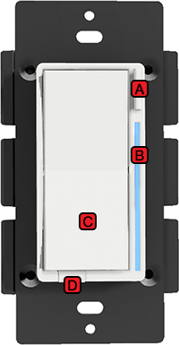
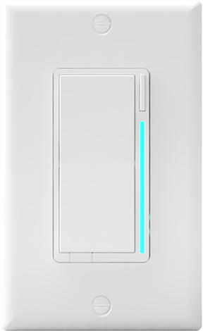
Figure 1.1 - LZW31-SN Switch Highlights
A. Config Button: This button is used to enter the configuration menu on your switch. When you hold it down for 10-15 seconds, the LED Bar (B) will light up Yellow to indicate you’re in config mode. Then follow the config menu on Page 10 to configure your switch to the way you’d like. In addition, the Config Button can be used to set your favorite scene*. Once your scene is setup, simply tap the button 1x and the scene will trigger.
B. RGB LED Notification Bar: This LED bar does multiple things. It serves as a visual display for the dimness level of your lights as well as offering visual notifications based on events that are setup via your HUB/Gateway* (ex: if your garage door is opened past 10pm, the LED Bar can blink Red). The bar can be further configured to be either disabled or set to a certain brightness level as shown on Page 10. Finally, the bar can be used to test Z-Wave Signal by holding the Config Button (A) for 5-10 seconds (Red = Not in Range, Green = In Range).
C. Responsive Paddle: The paddle works similar to a standard dimmer switch in that when you hold either up/down, the light switch will dim the lights to the level you’d prefer. However, when you tap the switch up, it will turn the light on to the last dim level and when you tap the switch down, it will shut the light off. The paddle can also act as a scene controller*. You may add up to ten (10) different scenes (Tap up 1x, 2x, 3x, 4x, or 5x and Tap down 1x, 2x, 3x, 4x, or 5x). Finally, the paddle can be removed if you’d like to change colors.
D. Air Gap Switch: This will cut power to the load your switch is wired to (ie: light bulb).
NOT SHOWN: Energy Monitoring and Scene Control are built-in features of this switch as well.
Switch Logic
There are a couple of ways to configure your switch. The first is via the switch itself, while the second is via your HUB or Gateway. Please see Figure 1.2 to see which parameters can be changed locally.
| Parameter | # Times To Press Config Button | About | Version Released | Notes |
|---|---|---|---|---|
| 01 | 01 | Dimming SpeedHow fast or slow the light turns on when you hold the switch (ie: dimming from 10-20%, 80-60%, etc)0 = Instant On, 1 = 1 second, 2 = 2 seconds, etc NOTE: If using a dumb switch this parameter will not work when using the non-smart side of the setup |
1.35+ | |
| 05 | 02 | Minimum Dim LevelMinimum level the light switch will dim to (great for fixing flickering bulbs)1 = 1%, 2 = 2%, 45 = 45%, etc |
1.35+ | |
| 06 | 03 | Max Dim LevelMaximum level the light switch will dim to55 = 55%, 56 = 56%, 99 = 99%, etc. |
1.35+ | |
| 07 | 04 | Invert SwitchInverts the switch (Tap Down = On, Tap Up = Off)0 = Disabled, 1 = Enabled |
1.35+ | Local config removed in 1.45+ (remote still available) |
| 09 | 05 | Default Level (Local)Default dim level for the switch when pressed locally (at the switch) - used for easy access for your favorite dim level or to create an automation to have your light only turn on to x% late at night0 = Switch returns to level it was prior to being off, 1 = 1%, 2 = 2%, 99 = 99%, etc. |
1.35+ | Local config removed in 1.45+ (remote still available) |
| 11 | 07 | Power On StateWhen power is restored, the switch reverts to either On, Off, or Last Level0 = Off, 1-99 = Specific % (dim level) On, 101 = Returns to level prior to power outage |
1.35+ | |
| 13 | 08 | LED Indicator ColorThis will set the default color of the LED BarCalculated by using a hue color circle. See here for details: Nathan Fiscus Switch Toolbox Use the slider bar by the word, “color” and your value can be found where it says, “(Color Value - Parameter 13)” |
1.35+ | |
| 14 | 09 | LED Indicator IntensityThis will set the intensity of the LED bar (ie: how bright it is)0 = Off, 1 = Low, 5 = Medium, 10 = High |
1.35+ | |
| 15 | 10 | LED Indicator Intensity (When Off)This will set the intensity of the LED bar (ie: how bright it is)0 = Off, 1 = Low, 5 = Medium, 10 = High |
1.35+ | |
| 17 | 11 | LED Indicator TimeoutChanges the amount of time the RGB Bar shows the Dim level if the LED Bar has been disabled0 = Always off, 1 = 1 second after level is adjusted, 10 = 10 seconds after level is adjusted |
1.35+ | |
| 21 | 12 | AC Power TypeUse to select whether or not your switch is wired in a neutral or non-neutral setup0 = Non-Neutral, 1 = Neutral |
1.35+ | |
| 22 | 13 | Switch TypeUse to select what scenario your switch is wired – single pole, multi-switch w/dumb (existing) switch, or multi-switch w/auxiliary (add-on) switch0 = Single-Pole, 1 = Multi-Switch Setup (Dumb/Existing), 2 = Multi-Switch Setup (Aux/Add-On) |
1.35+ | |
| _____________ | _____________ | ______________________________________ | ____________ | ______________________________________________________ |
Figure 1.2 - Parameters that can be changed locally
Using the chart above, let’s explore the logic behind how to change the switch parameters locally. Let’s walk you through a high level example, then follow up with a specific one.
Before exploring this, remember the following:
- Short press = 1x integers
- Hold 3 seconds = 10x integers
Ex: if you want to select parameter 13, you would hold 3 seconds and then tap (short press) 3x.
High-Level
Please see the below instructions to understand the high-level logic behind changing certain parameters locally at the switch:
- To enter configuration mode, hold down the config button (A) for 10-15 seconds and the LED Bar (B) will light up YELLOW
- From here, refer to the chart above (Figure 1.2) to see what parameter you’d like to change and tap the config button that many times (look at the, “Parameter” column to find the parameter you’d like to change and then go one column to the right (# Times To Press Config Button) to see how many times you need to press the Config Button (A). For example: If you want to change the Maximum Dim Level, press the config button (A) 3x or if you want to change the, “Power On State”, press the Config Button (A) 7x and so on).
- Once your parameter has been selected, the LED Bar (B) will blink YELLOW (it will correspond to the parameter you select)
- Fast Blink = 1x integers
- Long Blink = 10x integers
- Ex: 6 = 6x Fast Blinks, 13 = 1x Long Blink + 3x Fast Blinks
- Finally, once you’ve settled on a customization you like, it’s time to save your configuration settings. To do this, hold the config button (A) again for 10 seconds and the LED Bar (B) will light up YELLOW (release it) and then it will blink CYAN to confirm the settings are saved.
Specific Example

In the above example, we will change the minimum dim level to 45%. Please follow the below instructions to change the minimum dimmer level:
- Hold the Config Button (A) for 10 seconds to enter config mode (LED Bar will light up YELLOW and by default it will blink 1x since it starts out on Parameter 1)
- Looking at Figure 1.2, you’ll notice that to edit, “Minimum Dim Level”, you need to tap the config button 2x
- After tapping the Config Button (A) 2x, the LED Bar (B) will blink YELLOW twice to confirm
- The parameter chart shows that the Minimum Dim Level has a range of 1-45%. Each tap of the switch = 1 unit of measurement (in this case %) and each hold of 3 seconds = 10 seconds, so you’d hold on the UP Paddle for 3 seconds (then release) - 4x (ie: hold for 3 seconds, release, hold for 3 seconds, etc) and then tap UP 5x on the paddle to reach 45%.
- NOTE: You should see the LED bulb turn on as well – if you see it turn on before 45%, please stop and set it at that level
- As you are moving up to reach your desired %, the LED bar will give you feedback by blinking PURPLE (same logic as above with the YELLOW – LED bar should slow blink 4x and then fast blink 5x PURPLE).
- Now, we’ll save this configuration by holding down on the Config Button (A) for 10-15 seconds and the LED Bar (B) will turn GREEN and then YELLOW – release the button at YELLOW and it will turn CYAN to confirm the Parameter has been saved.
Hardware Info
Features
- Technology: Z-Wave Plus, S2 Encryption, SmartStart
- Z-Wave Chip: 500 Series
- 3-Way, 4-Way (Multi-Switch) Compatibility: Works with a dumb (existing) on/off switch (no dimming), auxiliary switch (GE or HomeSeer), or another Inovelli smart switch (via Z-Wave Association)
- Energy Monitoring: Monitors energy consumption
- Z-Wave Scene Enabled: Add up to 13 Z-Wave Scenes (ie: multi-tap to trigger a scene/routine directly from the switch)
- RGB Notifications: LED bar will notify you of certain events (ie: LED bar lights up red when front door is unlocked)
- Disable Local Control: Tap 8x on the config button to disable remote control
- Change Parameters Locally: Change parameters directly from the switch without the need for a Hub
- Accessories Included: White Faceplates/Paddles and a Neutral Wire Jumper (Almond not included)
Specs
- Neutral Wire Required: No (but recommended)
- Driver Type: MOSFET
- Leading/Trailing Edge: Leading Edge
-
Max Wattage: See below – maximum will vary based on bulb type and whether the heat sink tabs are removed or not
- Heat Sink Tabs Not Removed: 400W Incandescent, 300W LED, 150W CFL
- One (1) Side Heat Sink Tabs Removed: 300W Incandescent, 200W LED, 150W CFL
- Two (2) Sides Heat Sink Tabs Removed: 200W Incandescent, 150W LED, 100W CFL
- Min Wattage: If neutral wire is used, there is no minimum wattage required. However, if no neutral is installed, there needs to be at least 25W for the switch to work
- Use with Fan: No
- Power: 120V AC, 60 Hz
- Operating Temperature: 32-104 °F (0-40 °C)
- Signal Frequency: 908.42 MHz
- Range: Up to 100 meters line of sight between the Wireless Controller (Hub) and the closest Z-Wave Module
- Indoor/Outdoor Use: Indoor use only.
Firmware Info
Parameters
| Parameter | Config Locally | About | Range | Default | Size (Bytes) | Version Released | Notes |
|---|---|---|---|---|---|---|---|
| 01 | Yes | Dimming SpeedHow fast or slow the light turns on when you hold the switch (ie: dimming from 10-20%, 80-60%, etc)0 = Instant On, 1 = 1 second, 2 = 2 seconds, etc NOTE: If using a dumb switch this parameter will not work when using the non-smart side of the setup |
0-100 | 3s | 1 | 1.35+ | |
| 02 | No | Dimming Speed (Z-Wave)How fast or slow the light turns on when you adjust the switch remotely (ie: dimming from 10-20%, 80-60%, etc)0 = Instant On, 1 = 1 second, 2 = 2 seconds, etc. 101 = Keep in sync with Parameter 1 |
0-101 | 101 | 1 | 1.35+ | |
| 03 | No | Ramp RateHow fast or slow the light turns on when you press the switch 1x to bring from On to Off or Off to On0 = Instant On, 1 = 1 second, 2 = 2 seconds, etc. 101 = Keep in sync with Parameter 1 |
0-101 | 101 | 1 | 1.35+ | |
| 04 | No | Ramp Rate (Z-Wave)How fast or slow the light turns on when you bring your switch from On to Off or Off to On remotely0 = Instant On, 1 = 1 second, 2 = 2 seconds, etc. 101 = Keep in sync with Parameter 1 |
0-101 | 101 | 1 | 1.35+ | |
| 05 | Yes | Minimum Dim LevelMinimum level the light switch will dim to (great for fixing flickering bulbs)1 = 1%, 2 = 2%, 45 = 45%, etc |
1-45 | 1 (%) | 1 | 1.35+ | |
| 06 | Yes | Max Dim LevelMaximum level the light switch will dim to55 = 55%, 56 = 56%, 99 = 99%, etc. |
55-99 | 99 (%) | 1 | 1.35+ | |
| 07 | Yes* | Invert SwitchInverts the switch (Tap Down = On, Tap Up = Off)0 = Disabled, 1 = Enabled |
0-1 | 0 (Disabled) | 1 | 1.35+ | Local config removed in 1.45+ (remote still available) |
| 08 | No | Auto-off TimerAutomatically turns the switch off after x amount of seconds0 = Disabled, 1 = 1 second, 2 = 2 seconds, 32767 = 32767 seconds |
0-32767 | 0 (Disabled) | 1 | 1.35+ | |
| 09 | Yes* | Default Level (Local)Default dim level for the switch when pressed locally (at the switch) - used for easy access for your favorite dim level or to create an automation to have your light only turn on to x% late at night0 = Switch returns to level it was prior to being off, 1 = 1%, 2 = 2%, 99 = 99%, etc. |
0-99 | 0 (Previous) | 1 | 1.35+ | Local config removed in 1.45+ (remote still available) |
| 10 | No | Default Level (Z-Wave)Default dim level for the switch when turned on remotely - used for easy access for your favorite dim level or to create an automation to have your light only turn on to x% late at night0 = Switch returns to level it was prior to being off, 1 = 1%, 2 = 2%, 99 = 99%, etc. |
0-99 | 0 (Previous) | 1 | 1.35+ | |
| 11 | Yes | Power On StateWhen power is restored, the switch reverts to either On, Off, or Last Level0 = Off, 1-99 = Specific % (dim level) On, 101 = Returns to level prior to power outage |
0-101 | 0 (Off) | 1 | 1.35+ | |
| 12 | No | Association BehaviorWhen should the switch send commands to associated devices:01 = Local, 02 = 3-Way, 03 = 3-Way & Local, 04 = Z-Wave HUB, 05 = Z-Wave HUB & Local, 06 = Z-Wave HUB & 3-Way, 07 = Z-Wave HUB & Local & 3-Way, 08 = Timer, 09 = Timer & Local, 10 = Timer & 3-Way, 11 = Timer & 3-Way & Local, 12 = Timer & Z-Wave HUB, 13 = Timer & Z-Wave HUB & Local, 14 = Timer & Z-Wave HUB & 3-Way, 15 = All |
0-15 | 15 | 1 | 1.35+ | |
| 13 | Yes | LED Indicator ColorThis will set the default color of the LED BarCalculated by using a hue color circle. See here for details: Nathan Fiscus Switch Toolbox Use the slider bar by the word, “color” and your value can be found where it says, “(Color Value - Parameter 13)” |
0-255 | 170 (Blue) | 2 | 1.35+ | |
| 14 | Yes | LED Indicator IntensityThis will set the intensity of the LED bar (ie: how bright it is)0 = Off, 1 = Low, 5 = Medium, 10 = High |
0-10 | 5 | 1 | 1.35+ | |
| 15 | Yes | LED Indicator Intensity (When Off)This will set the intensity of the LED bar (ie: how bright it is)0 = Off, 1 = Low, 5 = Medium, 10 = High |
0-10 | 1 | 1 | 1.35+ | |
| 16 | No | LED Strip EffectThis will allow you to add some sweet effects to your LED bar (ie: pulse, chace, solid, etc)Byte 1 = Choose Color, Byte 2 = Choose Brightness Level, Byte 3 = Choose Effect, Byte 4 = Duration |
Varies | 0 | 4 | 1.35+ | |
| 17 | Yes | LED Indicator TimeoutChanges the amount of time the RGB Bar shows the Dim level if the LED Bar has been disabled0 = Always off, 1 = 1 second after level is adjusted, 10 = 10 seconds after level is adjusted |
0-10 | 3 | 1 | 1.35+ | |
| 18 | No | Active Power ReportsThe power level change that will result in a new power report being sent (% of previous report)0 = Disabled, 10 = 10% of previous report, 100 = 100% of previous report |
0-100 | 10 | 1 | 1.35+ | |
| 19 | No | Periodic Power & Energy ReportsTime period between consecutive power and energy reports being sent (in seconds)0 = 0 seconds, 1 = 1 second, 32767 = 32767 seconds Timer resets after every report is sent |
0-32767 | 3600s | 2 | 1.35+ | |
| 20 | No | Active Energy ReportsThe energy level change that will result in a new energy report being sent (% of previous report)0 = Disabled, 10 = 10% of previous report, 100 = 100% of previous report |
0-100 | 10 | 2 | 1.35+ | |
| 21 | Yes | AC Power TypeUse to select whether or not your switch is wired in a neutral or non-neutral setup0 = Non-Neutral, 1 = Neutral |
0-1 | 1 | 1 | 1.35+ | |
| 22 | Yes | Switch TypeUse to select what scenario your switch is wired – single pole, multi-switch w/dumb (existing) switch, or multi-switch w/auxiliary (add-on) switch0 = Single-Pole, 1 = Multi-Switch Setup (Dumb/Existing), 2 = Multi-Switch Setup (Aux/Add-On) |
0-2 | 0 | 1 | 1.35+ | |
| 50 | No | Multi-Tap Delay ConfigurationChanges the millisecond delay between consecutive taps (default is 700ms)1 = 100ms, 2 = 200ms, 9 = 900ms, etc Requires firmware 1.49 and above. |
1-9 | 7ms | 1 | 1.49+ | |
| 51 | No | Multi-Tap Delay On/OffRemoves the 700ms delay needed to detect multi-taps for scene control (if you turn this off, you will lose partial scene control)0 = No delay, 1 = 700ms delay Requires firmware 1.47 and above. |
0-1 | 1 (Delay) | 1 | 1.47+ | |
| 52 | No | Switch Mode0 = Normal operation1 = On /Off Mode - Switch will either be in the state of 0% power or 99% power, not allowing dimming. Useful for non-dimmable bulbs or other unique loads 2 = Smart Bulb - Switch always at 99% for use with loads like an Inovelli Bulb or Philips Hue Bulb. Use in conjunction with associations or scenes to achieve an awesome smart bulb experience Requires firmware 1.47 and above. |
0-2 | 0 (Off) | 1 | 1.47+ | |
| _________ | __________ | _______________________________________ | ________ | ____________ | ________ | _______ | _______________________________________________________ |
Command Classes
| # | Command Class |
|---|---|
| 5E | COMMAND_CLASS_ZWAVEPLUS_INFO |
| 26 | COMMAND_CLASS_SWITCH_MULTILEVEL |
| 70 | COMMAND_CLASS_CONFIGURATION |
| 85 | COMMAND_CLASS_ASSOCIATION |
| 59 | COMMAND_CLASS_ASSOCIATION_GRP_INFO |
| 55 | COMMAND_CLASS_TRANSPORT_SERVICE |
| 86 | COMMAND_CLASS_VERSION |
| 72 | COMMAND_CLASS_MANUFACTURER_SPECIFIC |
| 5A | COMMAND_CLASS_DEVICE_RESET_LOCALLY |
| 73 | COMMAND_CLASS_POWERLEVEL |
| 98 | COMMAND_CLASS_SECURITY |
| 9F | COMMAND_CLASS_SECURITY_2 |
| 5B | COMMAND_CLASS_CENTRAL_SCENE |
| 6C | COMMAND_CLASS_SUPERVISION |
| 32 | COMMAND_CLASS_METER |
| 75 | COMMAND_CLASS_PROTECTION |
| 22 | COMMAND_CLASS_APPLICATION_STATUS |
| 7A | COMMAND_CLASS_FIRMWARE_UPDATE_MD |
Association Groups
| Grouping Identifier | Max Nodes | Send Commands |
|---|---|---|
| Group 1 | 0x05 | 1. Central Scene Notification |
| Group 1 | 0x05 | 2. Basic Report |
| Group 1 | 0x05 | 3. Multilevel Report |
| Group 1 | 0x05 | 4. Application Status |
| Group 1 | 0x05 | 5. Device Reset Locally |
| Group 2 | 0x05 | Basic Set |
| Group 3 | 0x05 | Switch Multilevel Set |
| Group 4 | 0x05 | Switch Multilevel Set |
Button Mapping
The Red Series Dimmer has Scene Control built in which allows you to send a Z-Wave Central Scene Command to your hub/gateway (ie: double-tap, triple-tap, etc). Below is what’s used to determine how to assign scenes to your switch via buttons.
| Action | Button # | Event |
|---|---|---|
| Tap Up on Light Paddle 1x | 1 | Pushed |
| Tap Up on Light Paddle 2x | 2 | Pushed |
| Tap Up on Light Paddle 3x | 3 | Pushed |
| Tap Up on Light Paddle 4x | 4 | Pushed |
| Tap Up on Light Paddle 5x | 5 | Pushed |
| Hold Up on Light Paddle | 6 | Pushed |
| Hold Up and Release on Light Paddle | 8 | Pushed |
| Tap Down on Light Paddle 1x | 1 | Held |
| Tap Down on Light Paddle 2x | 2 | Held |
| Tap Down on Light Paddle 3x | 3 | Held |
| Tap Down on Light Paddle 4x | 4 | Held |
| Tap Down on Light Paddle 5x | 5 | Held |
| Hold Down on Light Paddle | 6 | Held |
| Hold Down and Release on Light Paddle | 8 | Held |
| Tap Config Button 1x | 7 | Pushed |
Change-Logs
Please see the following URL for the firmware change-logs: LZW31-SN Firmware Change-Logs
Quick Setup Instructions
Before starting the inclusion/pairing process, please make sure your switch is physically installed in the wall and power is turned on (LED bar should be solid blue).- Start the inclusion process on your hub/gateway
- Press the config button (A) three times rapidly (the LED bar should pulse blue to indicate the switch is in inclusion/pairing mode)
- If the switch includes successfully, the LED bar will turn solid green for two seconds
- The LED bar will turn solid red for two seconds of inclusion/pairing is unsuccessful. If this is the case, please try excluding (hyperlink) or factory resetting (hyperlink) the switch and try again to include/pair.
If you continue to experience issues including/pairing your switch, please ensure the switch is within Z-Wave range (insert url to range tester info).
For specific hub/gateway instructions, please click here.
Installation & Setup
Installation Preparation
About Z-Wave
Z-Wave is an incredible technology. With it powering your home, you can choose from over 600 companies and 2100 products, all of which will work with each other. The more devices, the more stable the network. The purpose of this portion of the manual is to help you understand how Z-Wave works (in layman’s terms) as well as help you organize an efficient Z-Wave network, setting you up for success in the long run. After-all, we’re assuming you’ll want more than one smart home device!
Range Estimator Tool
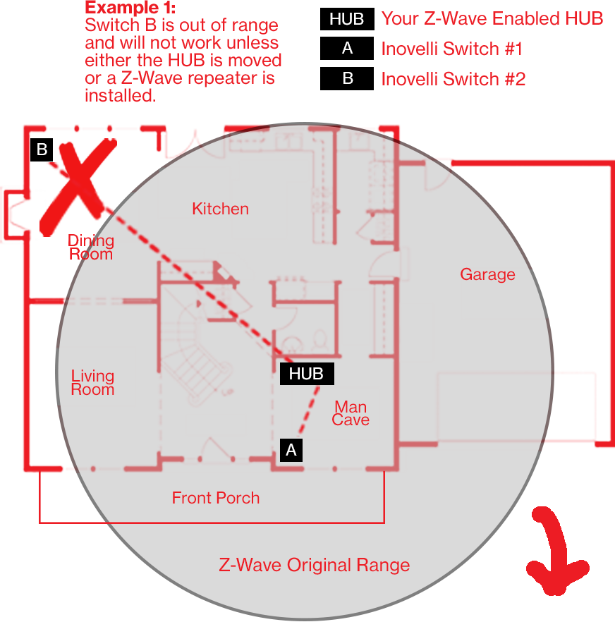
As referenced in the intro, Z-Wave can be used with a few devices or it can be used to build a large network. Below you’ll see two examples. In the first example, a user has a HUB which is looking for Z-Wave devices within its radius. Z-Wave devices outside this radius will not be found and need to either be moved within the radius or use a repeating device to reach it. The second example shows how a repeater can be used to reach a device outside of the initial radius. Keep this in mind when building your own network and make sure to use the range estimator below.
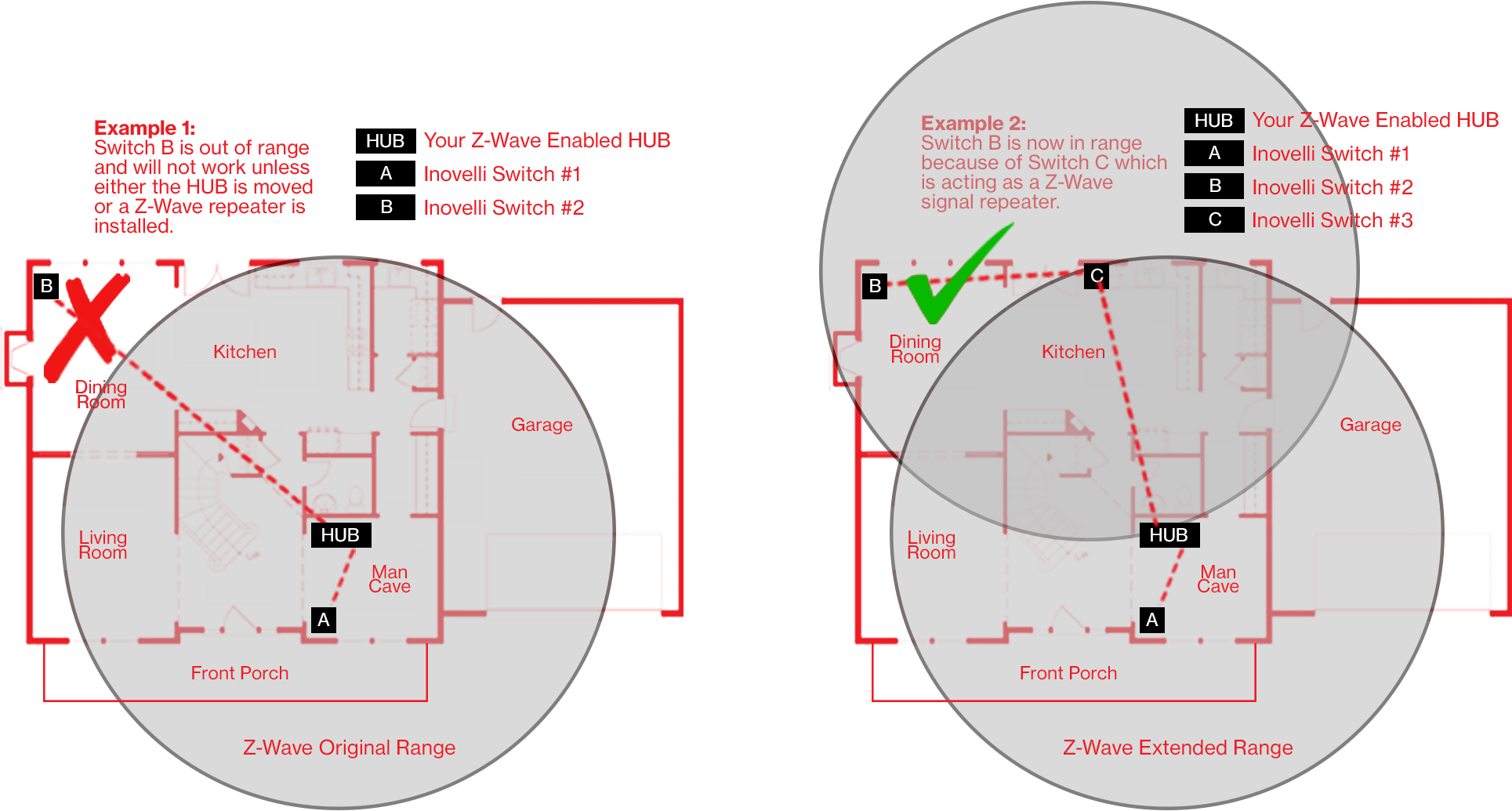
NOTE: Z-Wave range will never be a perfect circle due to walls, furniture, etc. The above is for reference only – please use the, “Range Estimator” and worksheet below for a better idea of where to place your switch or whether or not your chosen location will be in range.
Please use the below information to determine the depreciation of the Z-Wave signal. Z-Wave devices should have a distance of approximately 100m (328ft) without any obstacles in the way. Using the below information, if a signal has to travel through an inner wall, it will lose approximately 40% of its signal. Therefore, 100m multiplied by (100% - 40%) = 60m (197ft). Do this for every wall, window, etc and you will have your approximation. There’s a worksheet on Page 3 that will help. As always, this is just an estimate. Depending on the manufacturer’s quality for your other Z-Wave products, your signal may vary.
| Material | Thickness | Signal Depreciation |
|---|---|---|
| Aerated Concrete Stone | < 30cm // 11.8" | 20% |
| Aluminum Coating | < 1mm // 0.04" | 100% |
| Ceiling | < 30cm // 11.8" | 70% |
| Furniture (non-wood) | < 30cm // 11.8" | 40-60% |
| Glass (w/out metal coating) | < 5cm // 2.0" | 10% |
| Inner Wall | < 30cm // 11.8" | 40% |
| Iron Reinforced Concrete | < 30cm // 11.8" | 30-90% |
| Metal Grid | < 1mm // 0.04" | 90% |
| Outer Wall | < 30cm // 11.8" | 60% |
| Plaster | < 10cm // 3.9" | 10% |
| Pumice | < 30cm // 11.8" | 10% |
| Red Brick | < 30cm // 11.8" | 35% |
| Stone | < 30cm // 11.8" | 30% |
| Wood | < 30cm // 11.8" | 40-60% |
Z-Wave Distance Worksheet
Feel free to use the below worksheet to give an estimate on where you can put your Z-Wave Switch relative to your HUB (or other Z-Wave repeater). Below is an example of how to use the sheet, using, “Example 1” from above.
| Starting Distance | Obstacle | Signal Depreciation | Ending Distance |
|---|---|---|---|
| 100m // 328ft | Inner Wall | 40% | 60m // 197ft |
| 60m // 197ft | Inner Wall | 40% | 36m // 118ft |
| 36m // 118ft | Wood Stairs | 60% | 14m // 47ft |
| 14m // 47ft | Inner Wall | 40% | 9m // 28ft |
| 9m // 28ft | Wood Cabinet | 50% | 5m // 15ft |
| 5m // 15ft | Wood Table & Chairs | 60% | 2m // 7ft |
Figure 1.3 – Z-Wave Distance Worksheet Example
For the starting Distance, use 100m. Then look directly from your HUB to wherever you’d like to put the outlet and see what obstacles are in the way. Then list those obstacles on the worksheet above (Figure 1.3) – NOTE: Replace the numbers and words above with your own.
Best Practices For Installation
Now that you’ve read how to calculate the Z-Wave range and have determined the best location to put your switch, it’s important to understand some best practices of how to pair this device. Below are a few things to keep in mind when you start your individualized pairing instructions.
-
Please use a compatible, dimmable bulb. This switch uses MOSFET, Leading Edge technology, so only compatible bulbs will work. For a full list, see here: Bulb Compatibility App
-
Calculate the Maximum Distance From the Worksheet Above and Place Well Within That Distance
- Please use the worksheet above to calculate your maximum distance. This will save us both the headache of offline devices. Remember to add all objects that could potentially be in the way and it’s our recommendation to be conservative with the distance numbers.
-
If the Switch is Not Including, Try an Exclusion
- Z-Wave devices can only be included (paired) to one HUB at a time. Sometimes, what happens is that the factory tests the devices by including it to their network and forgets to remove the device from their network, causing the switch to believe that it’s paired to the factory HUB. While this is extremely rare, it may happen. This can also happen if you purchased this switch used. Follow the exclusion instructions located on Page 4 or 5 if you run into issues or check the range to make sure you are within range of the HUB. Or, if you’ve installed it already, simply hold down the config button for five (5) seconds to see whether or not the switch is within range. If it lights up GREEN and stays GREEN after you’ve let go, then it’s within range, however, if it lights up RED, then you are not within range.
Switch Wiring Instructions
Please remember – if you are unsure how to read a schematic or are unfamiliar with wiring, please consult an electrician as you can become severely injured. In addition, we are unable to give wiring advice. If you’d like help or advice, you may also post in the Wiring Discussion section.
Please-Read
Disclaimers & Statements
Wiring Warnings
Do not try installing this device if you are unsure of how electrical circuits operate within your home. As exciting as it is to have a smart switch installed, it can be dangerous and even life-threatening if you do not install this correctly. Please consult a qualified electrician if necessary as we are unable to give advice outside of schematics.
PLEASE NOTE: As of 05/25/19, we are unable to provide electrical and/or wiring advice outside of our schematics. If you are unable to read a schematic or are not familiar with wiring, we suggest hiring an electrician. We apologize for any inconvenience.
Product Warnings
CAUTION - PLEASE READ!
This device (LZW31-SN) is intended for installation in accordance with the National Electric Code and local regulations in the United States, or the Canadian Electrical Code and local regulations in Canada. If you are unsure or uncomfortable about performing this installation consult a qualified electrician.
CONTROLLING APPLIANCES & MOTORS
These dimming switches are NOT meant to control appliances. Please only use these for controlling dimmable lights (See: Bulb Compatibility App). In addition, please DO NOT USE TO CONTROL FANS as it will ruin your fan’s motor. These switches are not built to control a fan or any motor.
MEDICAL EQUIPMENT
Please DO NOT use this switch to control Medical or Life Support equipment. Z-Wave devices should never be used to control the On/Off status of Medical and/or Life Support equipment.
OTHER WARNINGS
Risk of fire, electrical shock and burns.
WARNING - SHOCK HAZARD
TURN OFF THE POWER to the circuit for the switch and lighting fixture at the service panel (circuit breaker) prior to installation. All wiring connections must be made with the POWER OFF to avoid personal injury and/or damage to the switch.
USING MULTIPLE SWITCHES IN THE SAME GANG-BOX
The metal plates surrounding the switch assembly are a heat sink. The maximum load rating (400W Incandescent, 300W LED and 150W CFL) is applicable when installed in a single gang-box with all six (6) tabs still in tact (See numbers 1-6 on Figure 1.4). To install multiple switches in a gang-box please remove the tabs on the outside. This can be done by removing either the left and/or right sides by using needle-nose pliers (clamp onto the tabs and wiggle back and forth until the tabs break off). Please see, “Max Wattage Key” for max wattage based on removing the tabs.
MAX WATTAGE KEY
This switch is designed for use only with permanently installed fixtures. If you are installing multiple smart switches in a gang-box, you will have to remove the heat sink tabs (#’s 1-6 shown in Figure 1.4). Doing so will reduce the maximum wattage available for your switch to control. Please see video below for the proper way to remove the heat sink tabs (again, you only need to do this if you’re putting your switch alongside other smart switches in a multi-switch gang-box):

To determine this new maximum wattage please use the following key:
- Tabs 1-6 NOT REMOVED = 400W Incandescent, 300W LED, 150W CFL
- Tabs 1-3 REMOVED = 300W Incandescent, 200W LED, 150W CFL
- Tabs 4-6 REMOVED = 300W Incandescent, 200W LED, 150W CFL
- Tabs 1-6 REMOVED = 200W Incandescent, 150W LED, 100W CFL
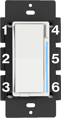
Figure 1.4 - Heat Sink Tabs
FCC Statements
FCC Caution: Any changes or modifications not expressly approved by the party responsible for compliance could void the user’s authority to operate this equipment. This device complies with Part 15 of the FCC Rules. Operation is subject to the following two conditions: (1) This device may not cause harmful interference, and (2) this device must accept any interference received including interference that may cause undesired operation.
NOTE: This equipment has been tested and found to comply with the limits for a Class B digital device, pursuant to Part 15 of the FCC Rules. These limits are designed to provide reasonable protection against harmful interference in a residential installation.
This equipment generates, uses and can radiate radio frequency energy and, if not installed and used in accordance with the instructions, may cause harmful interference to radio communications. However, there is no guarantee that interference will not occur in a particular installation. If this equipment does cause harmful interference to radio or television reception, which can be determined by turning the equipment off and on, the user is encouraged to try to correct the interference by one or more of the following measures: Reorient or relocate the receiving antenna, increase the separation between the equipment and receiver, connect the equipment into an outlet on a circuit different from that to which the receiver is connected or consult the dealer or an experienced radio/TV technician for help. This equipment should be installed and operated with minimum distance 8in (20cm) between the radiator and your body.
IC Caution: This device complies with Industry Canada license-exempt RSS standard(s). Operation is subject to the following two conditions: (1) this device may not cause interference, and (2) this device must accept any interference, including interference that may cause undesired operation of the device.
DECLARATION DE CONFORMITE D’INDUSTRIE CANADA: Ce périphérique a été testé et reconnu conforme aux limites spécifiées dans RSS-210. Son utilisation est soumise aux deux conditions suivantes: (1) il ne doit pas provoquer d’interférences gênantes et (2) il doit tolérer les interférences re.ues, notamment cellessusceptibles d’en perturber le fonctionnement.
Prerequisites
PLEASE READ THE PREREQUISITES BELOW:
- Neutral Wire is NOT Required (But Recommended)
- Inovelli switch needs to be installed where the Line (120V) is located
- Do not use an illuminated dumb switch as your secondary switch
-
Max wattage: See below – maximum will vary based on bulb type and whether the heat sink tabs are removed or not
- Heat Sink Tabs Not Removed: 400W Incandescent, 300W LED, 150W CFL
- One (1) Side Heat Sink Tabs Removed: 300W Incandescent, 200W LED, 150W CFL
- Two (2) Sides Heat Sink Tabs Removed: 200W Incandescent, 150W LED, 100W CFL
- Min Wattage: If neutral wire is used, there is no minimum wattage required. However, if no neutral is installed, there needs to be at least 25W for the switch to work
- Inductive Load (fans): Not for use with fans
Pro-Tips
Please read the following Pro-Tips:
- Remember to turn off the power prior to installation and ensure all connections are made prior to turning the power back on. No need to be a hero!
- The Line wire is Hot. Please use a multimeter to locate it.
- Please remember to Ground all connections
- Remember to start the inclusion process prior to flipping power back on (see specific hub instructions for more info).
- Use wire-strippers to strip away 1" of the wire for screw installations (wrap around screw), and 5/8" for terminal installation (insert in hole).
- DO NOT unscrew the screw completely. It will ruin the switch. Remember clockwise = tight, counter-clockwise = loosen
- If inserting the wire inside the terminal, please turn the screw counter-clockwise fully to loosen the plate – stick the wire inside the terminal and then tighten. The plate should tighten against the wire. Tug on the wire after to ensure it’s properly secure (see video below).

Warning
Not all wire colors shown may be the same as what’s in your box. While we’ve tried our best to match the most common setups, local electrical codes may be different than what’s depicted. If your wire colors do not match, please use a multi-meter to check for continuity, hire an electrician or post in our community where someone can help. Again, we are unable to give specific wiring advice ourselves due to liability issues.
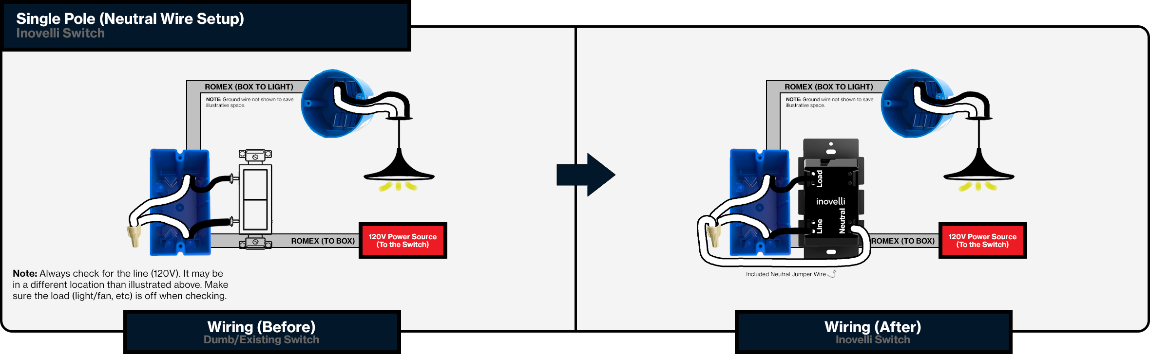
Single-Pole Installation
Single-pole means that you have one switch that controls a load/light.
Neutral Setup
Non-Neutral Setup

NOTE: if the load is under 25W, you will need to purchase and install a bypass at the light.
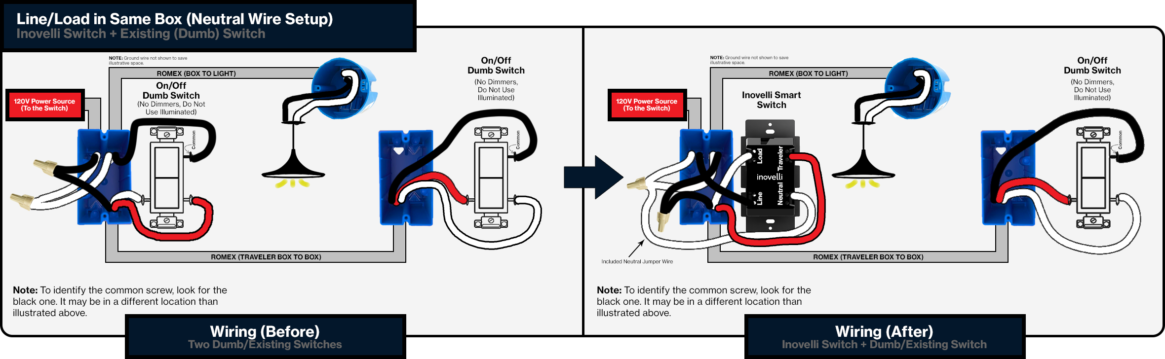
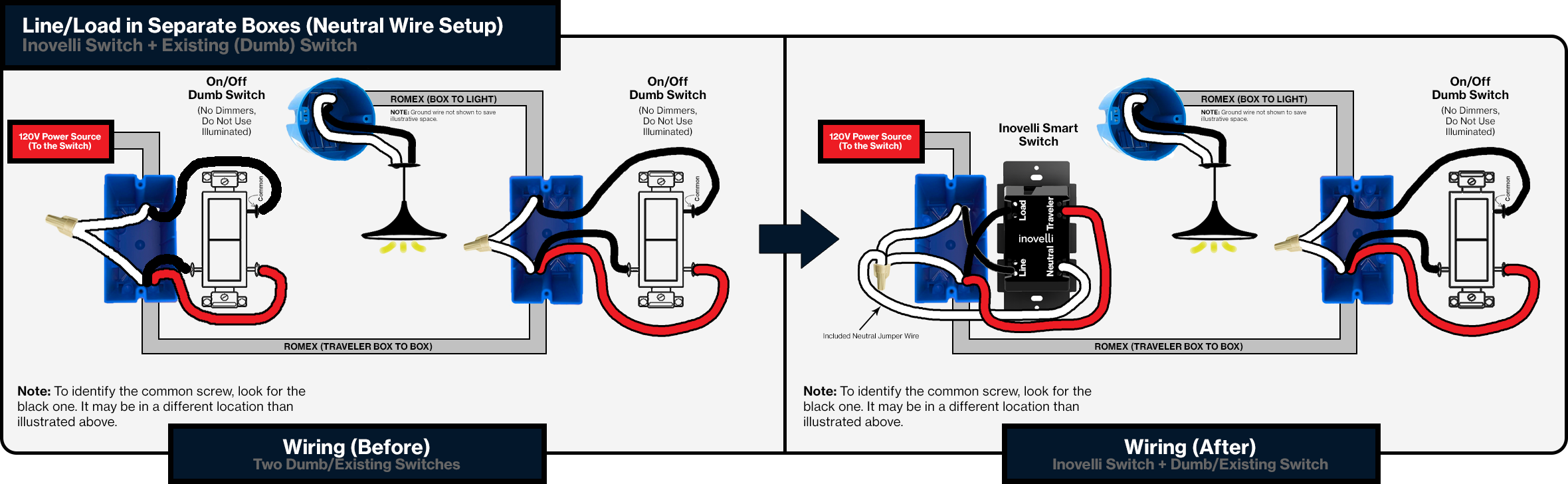
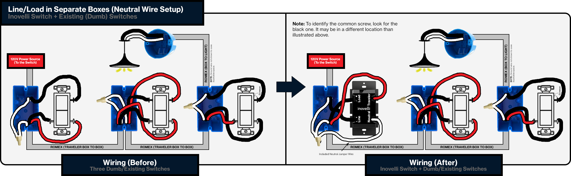
3-Way Installation
3-Way circuit means that you have two switches that controls a load/light. There are a couple of official options when installing 3-Way setups and one unofficial option.
- Smart Switch (Inovelli) + Dumb Switch - (Official Option)
- Install your smart switch and leave your existing switch at the other end
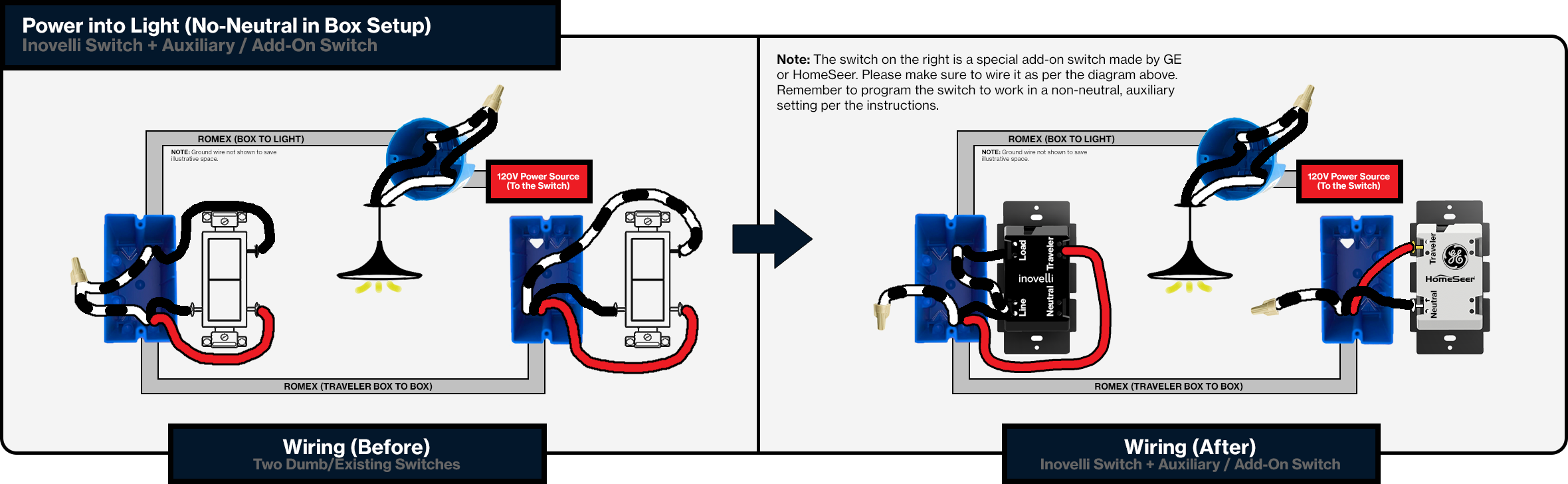
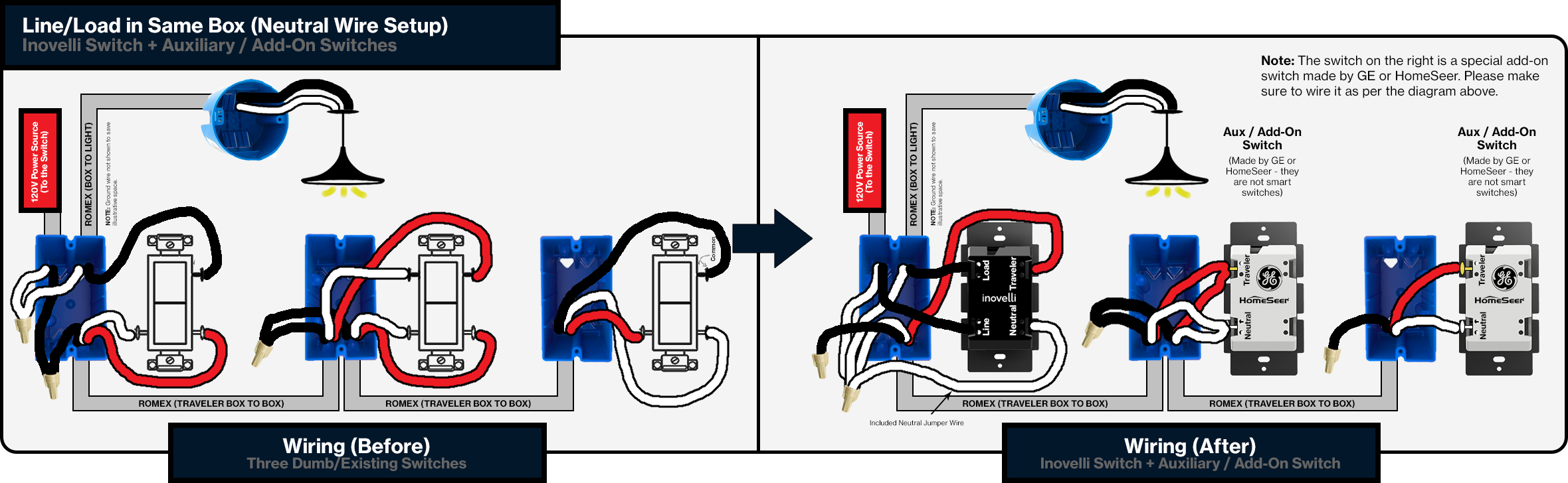
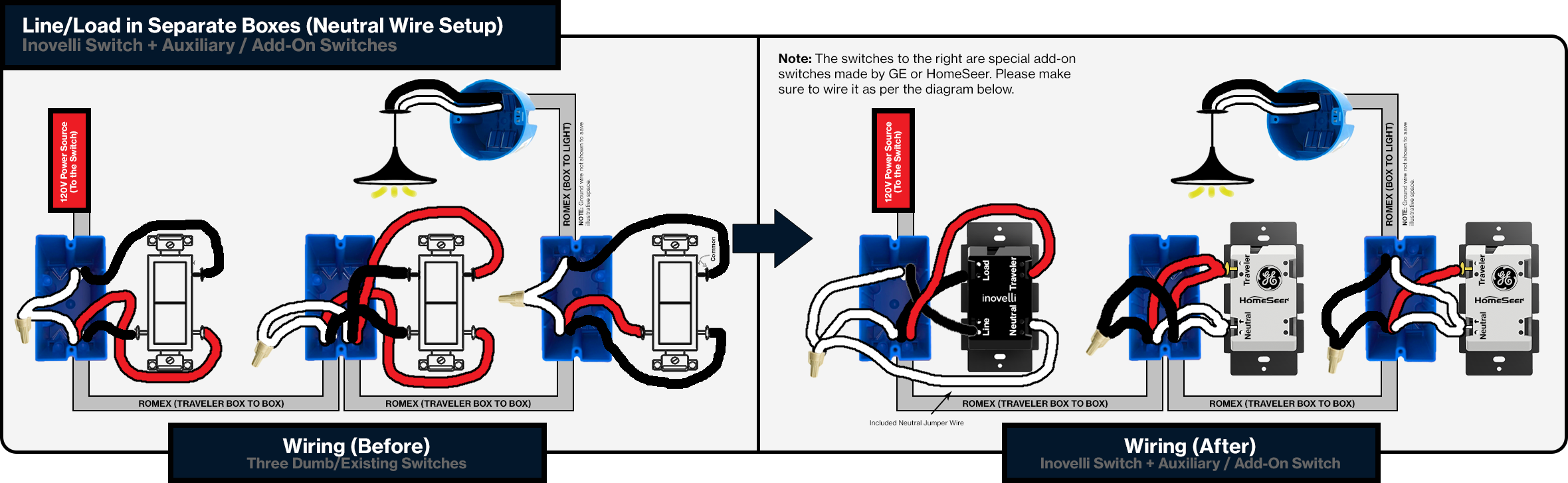
- Smart Switch (Inovelli) + Aux Switch - (Official Option)
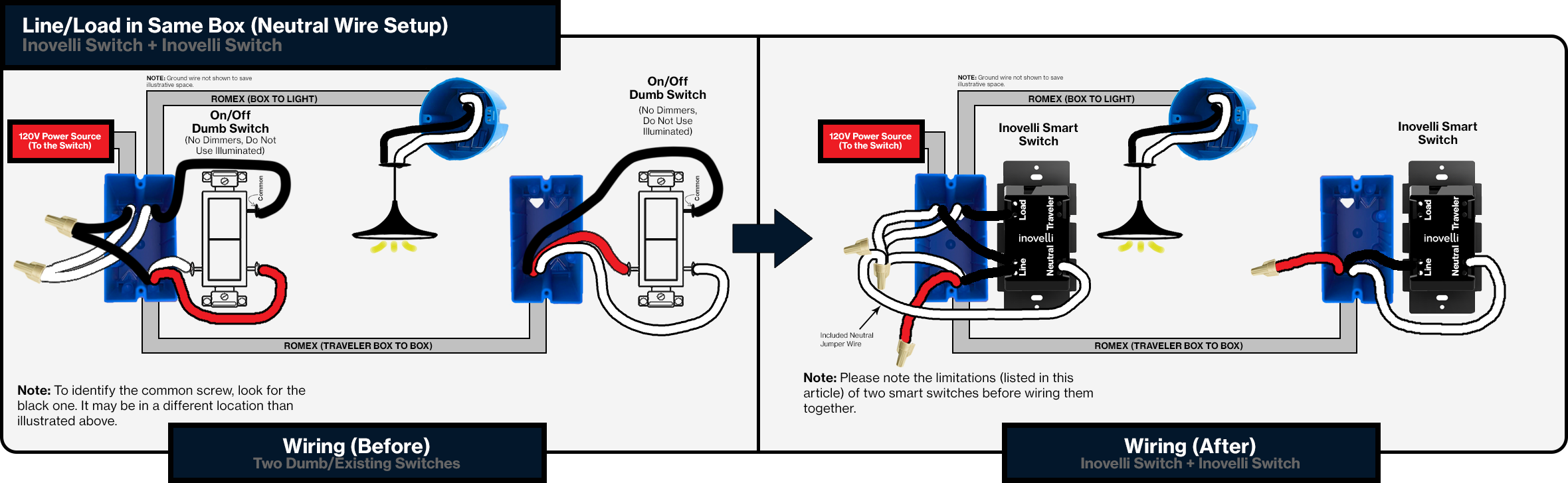
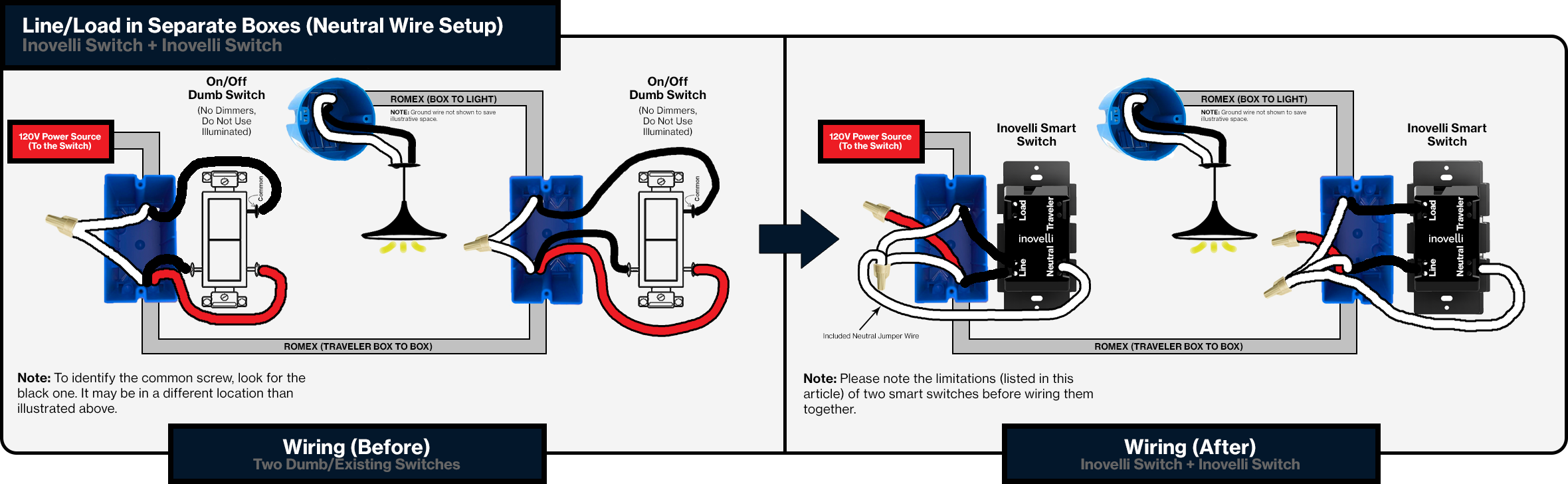
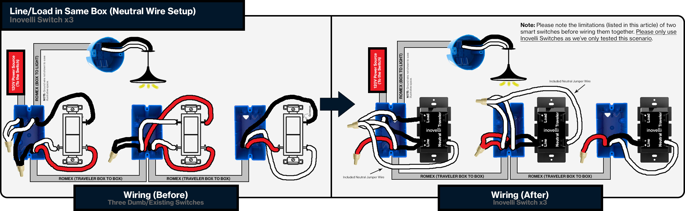
- Smart Switch (Inovelli) + Smart Switch (Inovelli) - (Unofficial Option - See Limitations Below)
- Depending on your hub, you may experience some lag due to the cloud
- You may have to rewire the load as well
- LED Bars may not sync properly
- Not officially tested by UL so proceed at your own risk
NOTE: You must use an auxiliary (add-on) switch if there is no neutral present in the circuit.
IMPORTANT: Once you install these, you will need to program them to work properly. In multi-switch setups, the smart switch needs to understand what setup it’s in (ie: neutral or non-neutral, dumb or aux). Programming instructions can be found here: (insert link)
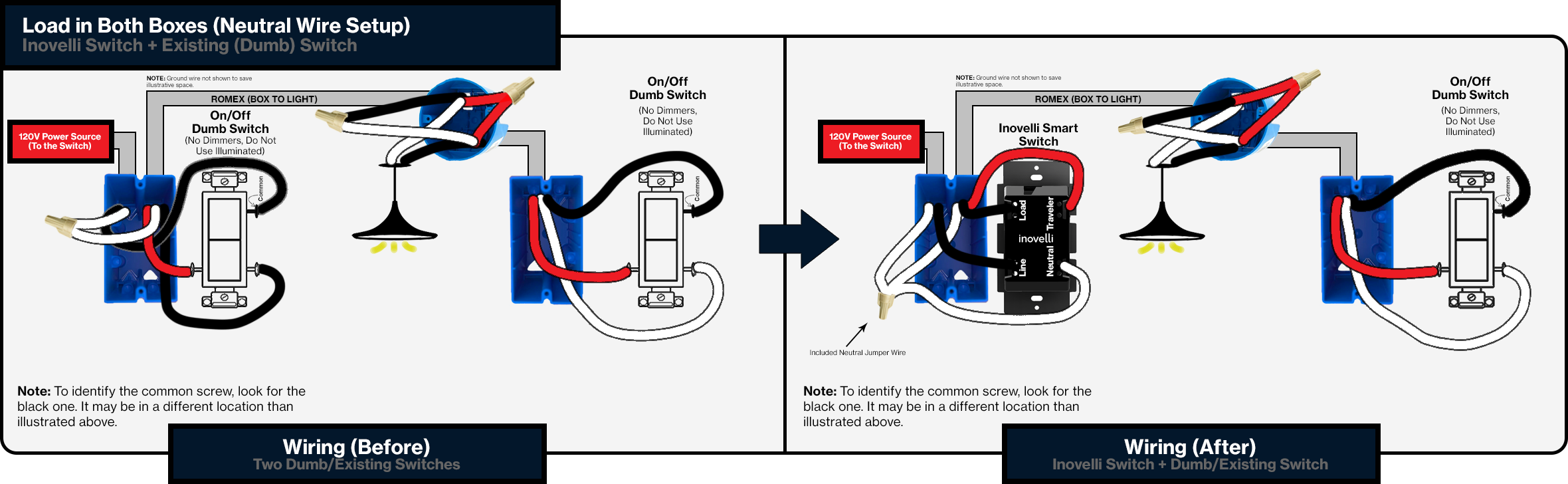
Dumb/Existing Switch
Neutral Setup
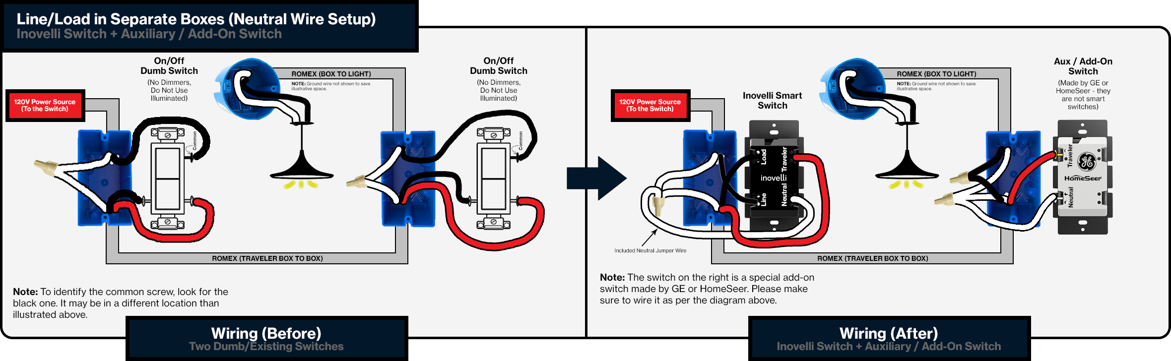
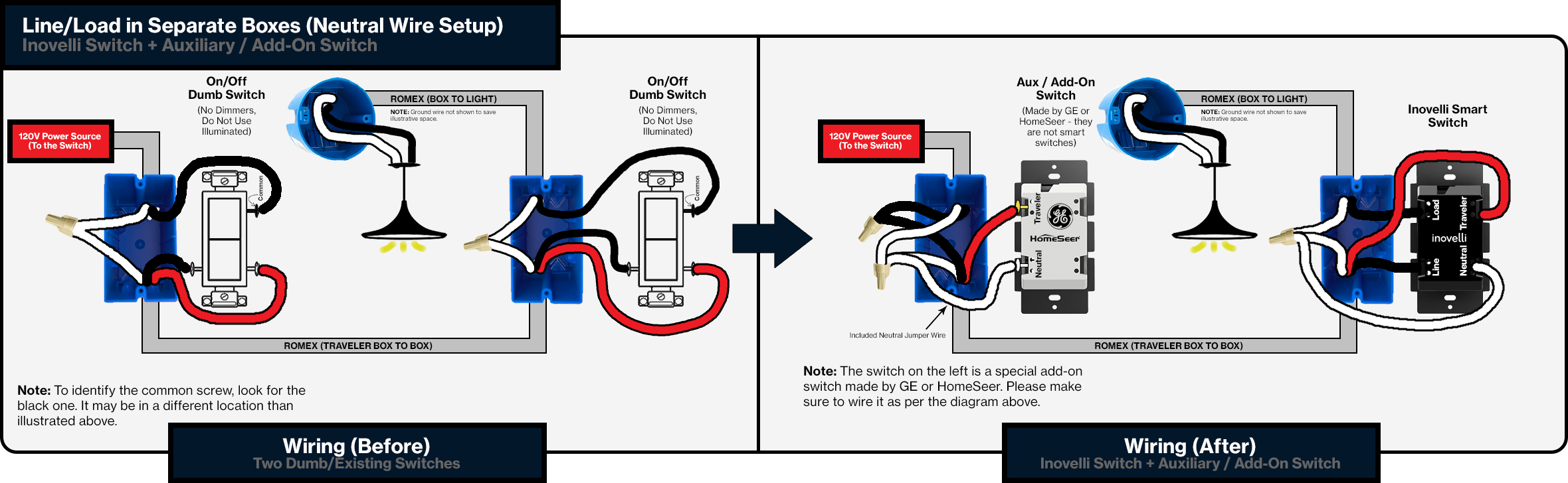
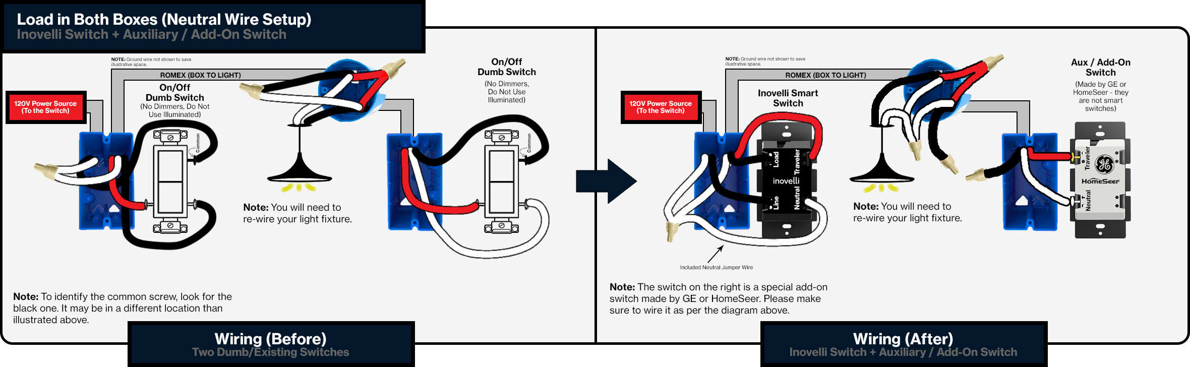
Aux/Add-On Switch
Neutral Setup

Non-Neutral Setup
2x Smart Switches
Please keep in mind, this is not an officially supported setup and by wiring it this way, the warranty is void. Proceed with caution and note the limitations here.
Neutral Setup
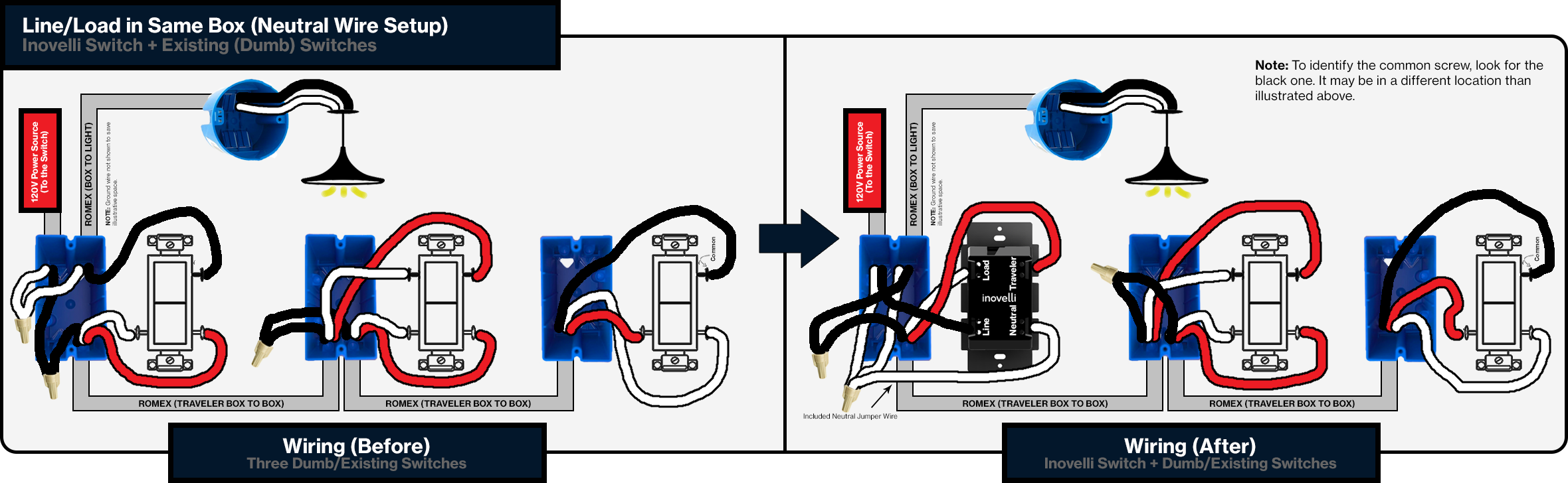
4-Way Installation
4-Way circuit means that you have three switches that controls a load/light. There are a couple of options when installing 4-Way setups.
- Smart Switch (Inovelli) + Dumb Switch
- Install your smart switch and leave your existing switch at the other end
- Smart Switch (Inovelli) + Aux Switch
NOTE: You must use an auxiliary (add-on) switch if there is no neutral present in the circuit.
IMPORTANT: Once you install these, you will need to program them to work properly. In multi-switch setups, the smart switch needs to understand what setup it’s in (ie: neutral or non-neutral, dumb or aux). Programming instructions can be found here: (insert link)
Dumb/Existing Switch
Neutral Setup
Aux/Add-On Switch
Neutral Setup
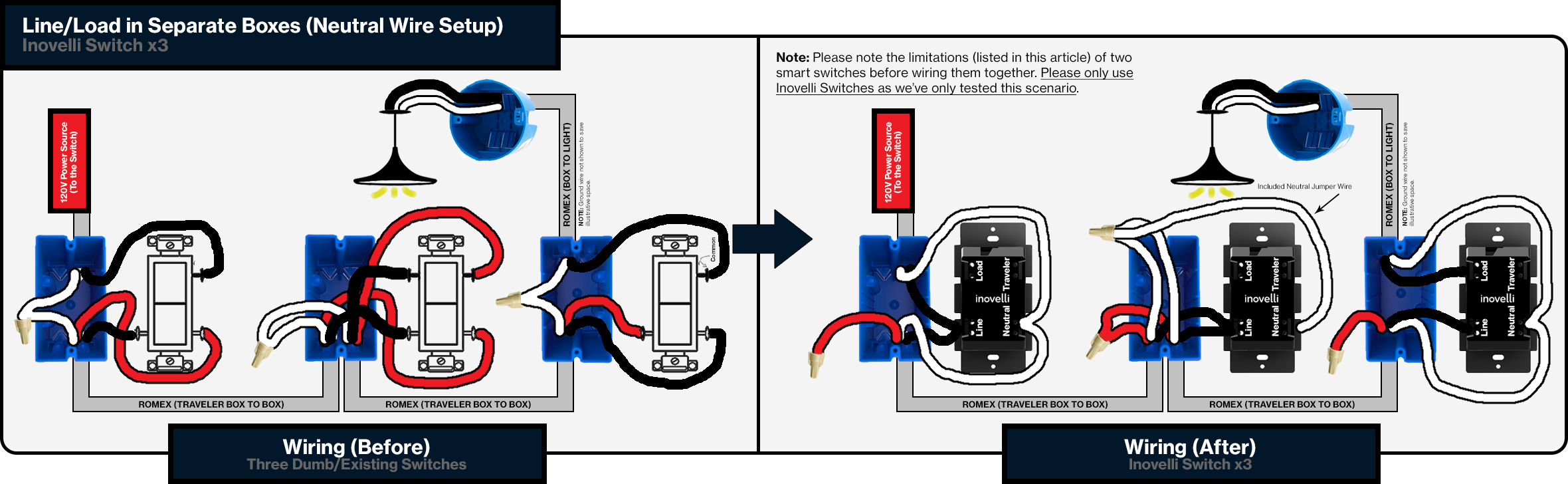
3x Smart Switches
Please keep in mind, this is not an officially supported setup and by wiring it this way, the warranty is void. Proceed with caution and note the limitations here.
Neutral Setup
Switch Inclusion / Exclusion / Resetting Instructions
Quick Instructions
Inclusion / Pairing
Before starting the inclusion/pairing process, please make sure your switch is physically installed in the wall and power is turned on (LED bar should be solid blue).
- Start the inclusion process on your hub/gateway
- Press the config button (Figure 1.1 - Button A) three times rapidly (the LED bar should pulse blue to indicate the switch is in inclusion/pairing mode)
- If the switch includes successfully, the LED bar will turn solid green for two seconds
- The LED bar will turn solid red for two seconds of inclusion/pairing is unsuccessful. If this is the case, please try excluding (hyperlink) or factory resetting (hyperlink) the switch and try again to include/pair.
Exclusion / Removal
- Start the exclusion process on your hub/gateway
- Press the config button (Figure 1.1 - Button A) three times rapidly (the LED bar should pulse blue to indicate the switch is in exclusion/removal mode)
- If the switch excludes successfully, the LED bar will turn solid green for two seconds
- The LED bar will turn solid red for two seconds of exclusion/removal is unsuccessful. If this is the case, please try factory resetting (hyperlink) the switch by holding the config button for 20 seconds (LED bar should turn solid red for 5 seconds).
Here’s an example of the cadence of pressing the config button to enter inclusion and exclusion mode (this is a SmartThings specific example, but the cadence remains the same):

Factory Reset
- Hold down on the config button (Figure 1.1 - Button A) for 20 seconds until the LED bar turns solid red
- Factory resetting should only be done if your hub is not responding or is non-existent. Please use the Exclusion process before trying to factory reset.
SmartThings
Since SmartThings is constantly improving and updating their platform, we’ve created a separate thread so that community members can help us keep the instructions up to date.
That said, please click here to be taken to the setup instructions: SmartThings Instructions
Hubitat
Since Hubitat is constantly improving and updating their platform, we’ve created a separate thread so that community members can help us keep the instructions up to date.
That said, please click here to be taken to the setup instructions: Hubitat Instructions (insert url)
Home Assistant
Since Home Assistant is constantly improving and updating their platform, we’ve created a separate thread so that community members can help us keep the instructions up to date.
That said, please click here to be taken to the setup instructions: Home Assistant (insert url)
HomeSeer
Since HomeSeer is constantly improving and updating their platform, we’ve created a separate thread so that community members can help us keep the instructions up to date.
That said, please click here to be taken to the setup instructions: HomeSeer (insert url)
Vera / Ezlo
Since Vera/Ezlo is constantly improving and updating their platform, we’ve created a separate thread so that community members can help us keep the instructions up to date.
That said, please click here to be taken to the setup instructions: Vera/Ezlo (insert url)
Wink
Since Wink is constantly improving and updating their platform, we’ve created a separate thread so that community members can help us keep the instructions up to date.
That said, please click here to be taken to the setup instructions: Wink (insert url)
Other
There are many other hub/gateway’s out there and it’s hard to keep up! If you don’t see your hub or gateway listed, please use the, “Quick Instructions” above. In addition, if you’d like to see your hub added, please reach out and we can either add instructions or ask the community to do so.
Warranty
For the most up to date information around your switch warranty, please see the following URL: https://inovelli.com/warranty-returns-price-matchSee Also
- French Manual (Coming Soon)
- Spanish Manual (Coming Soon)
- Bulb Compatibility App
Notes:
[1] If your hub is not listed, let us know and we can either create instructions or ask the community to do so.