Hi,
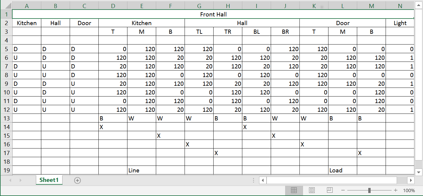
I’m not sure how other do this, but here’s where I start when trying to work out where my wires all go (this is a 4 way example). With a multi-meter, measure ground to each of the switch connections, for each possible combination of switch positions (my abbreviations for connection - T-top, M-middle, B-bottom & TL-TopLeft, BR-BottomRight…, U-up & D-down are the switch positions, and the light is 0-off, 1-on). Kitchen, Hall & Door are the 3 switches.
Look for columns that have exactly the same voltages - they must be 2 ends of the same wire (my bottom rows represent wires - X shows each end), as a double check, I’ve marked the wires as B-black or W-white at each connection (my house doesn’t seem to have any red travellers) - check that both ends of what you think are the same wire are the same color. One connection will be 120 all the time; there’s the line. One voltage should match the light status; there’s the load.
A drawing would be helpful. These diagrams might help and be a guide.
Note that the “middle” switch in a 4-way setup has 4 connections - I’m guessing that’s the “hall”. Use red electrical tape to mark the travelers - you can figure out which they are from the existing connections. Was this a professional installation? Are you in the USA?
Since power enters your circuit at the Kitchen, that’s where your smart switch will go. If you just want on-off control at the other two locations, you get line and load from the power cable, and connect the travelers/commons/load per Inovelli instructions.
If you want remote dimming and always up=on down=off at the remote locations by using two “companion” switches, repurpose one existing traveler as traveler throughout (splicing as necessary) and the white wire as neutral throughout (again splicing as necessary), and cap “common” everywhere.
Hi @PA94301,
Sorry, this was intended as an example of how I start the process; it’s here in case it’s any help to others. The intent of all these measurements is to be able to draw the diagram - those last lines with the 'X’s show which wires go where - you can diagram those if you like.
If anyone’s curious, in this particular case, I wanted the Inovelli switch in the kitchen (which also has neutral), so connected the Inovelli load to the black wire from the kitchen to the hall (line 14), connected to the black wire to the door (line 17), and to the actual load. Then I used the white wires (lines 15 & 16) to connect 2 add-on switches (other boxes have neutral too).
Hi John, @PA94301,
I’m equally curious as to how others start. You pull out the switches (3 in this case), what do you do next to work out which wires go where?
You have to look at how many Romex are connected to each switch and pay attention to how they are connected, particularly the conductor going to the common terminals on the switches. Photographing what you have to start with helps in case you need help here.
You first need to determine if you have a line (i.e. constant hot with a neutral in one of the boxes). For a 3-way, if you have two 2-wire Romex in the boxes in addition to a 3-wire, then it’s likely you do. This isn’t absolute, though, as it depends where the light is located, either between the switches or after them.
So if you have a line in the box, the black of a 2-wire will likely be connected to one of the common (black) terminals on the dumb switch. To confirm, pull the wire off the switch and test it using the white in the same Romex to see if it is constantly hot with the other switch(s) in both positions.
This is just a quick start explanation. Go to a site like http://www.electrical101.com/3way-switch-wiring-using-nm-cable.html and study the various configurations focusing on the number of Romex and conductors that are going to be in the boxes for the varying configurations. After a while, it becomes more obvious.
You can always post here and we can figure it out. When you post pictures, we want to see both the switches AND the wires inside of the boxes. Pull the switches out so it’s clear how they are coming into the box. Pictures of the dumb switches before you start are a plus.