3-way - boxes with 3 black wires all separate runs

Both boxes are identical.

I’d guess you have this configuration. Can you test with a DMM?
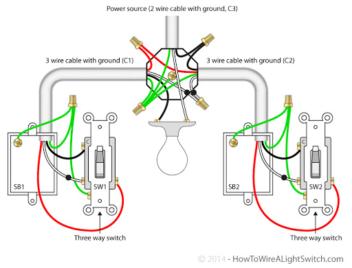
image

If that’s the case you need an aux for the non load side. Also need to rewire light.

Let me know if I’m reading the diagram correctly.

From SB2 the red and the white wire are traveler wires to SB2.
Black wire going into SB2 is the line.
At SB1 the black wire is the load wire.

If so I do believe that is exactly what I have and I will checkout the link you posted.

You got it

@stu1811 so in what you thought we would have both travelers going through the light switch, but that looks to not be the case for me. Here is a photo of the light.

The light has two bulbs so the two white and two blacks are just going to the separate bulbs.

I’m guessing what I have is SB1 → SB2 → Load

Hmm. What’s above that? There is probably a junction box somewhere that has the traveller. @Bry @harjms what do you think?

Definitely looks like there’s another box or light that needs to be found.

1 Like

Agreed. Is this the only light? If it’s the only light then there has to be another junction box. If you think about it, the hot that is being fed to this light has to be switched or it would never turn off. If there is more than one light being controlled, then you need to look in those boxes as well.

1 Like

Only a single light. I can pull down what is above it, but I don’t agree that this setup requires another junction.

SB1 has 2 travelers one of which would always be hot.
SB2 has those 2 incoming travelers and it always connects one of the two to the load.

Let’s say we have traveler 1 and traveler 2.
SB1 T1 is hot
SB2 T2 is switched to the load
Light is off

If you flip either switch the light would turn on.

To give more info. This light is at the top of the stairs. One switch is at the bottom and the other switch is at the top. Although I don’t think this info will help.

I’d have to disagree because I don’t see the extra wire set like originally thought at the ceiling light.

So you have three conductors in each of two switch boxes and two conductors at the light. The two conductors at the light are not the constant hot / neutral or the light would never turn off.

So that leaves your three conductors in each of the two switches. Presumably, one of the conductors in one of the switch boxes is constantly hot. If you don’t think there’s another jbox somewhere, then explain where your hot is coming from. It’s just not materializing at the switch.

The only other possible explanation would be if you have knob and tube wiring. Is that what you have?

I think we figured it out.

I’ve never used knob and tube. @bry briefed me on it.

I think you need an aux switch setup in a non neutral setup.

That 100% is knob and tube. There are most likely joints in the walls without boxes. Be very careful with it because it’s rather old and bending it can crack or damage the insulation. The bottom right box should have a tube coming into the box hole to protect the wire from the edges of the hole.

1 Like

@PJF it indeed does have a tube around the wire.

If all wires are disconnected.
SB1 1 of the 3 black wires is hot and that’s the constant line
SB2 0 of the 3 blacks are hot.

SB1 if I connect all 3 wires together. At SB2 now 2 of the wires are hot.

This is why I think SB1 has 2 travelers going to SB2 and SB2 goes to the load.

With that setup how would I wire a Aux and a Inovelli dimmer?

As for specifically saying knob and tube. At least in the basement looking at up the wiring, it has all been replaced, but it’s certainly possible this one switch is using much older wiring. The house is from the early 1900s.

You should be able to do it with an Aux switch. @harjms will post the full solution.

The one thing to double-check either using a continuity test or toning is to make sure the two conductors in the box with the hot go directly to the other switch box.

I believe it would look similar, but basically Inovelli would have to go into the load box (SB2). Auxxswitch would go in line box. Line would connect to aux switch neutral port, and also one of the travelers as this will feed line to the dimmer. The other traveler will connect to traveler port and connect to the traveler on the Inovelli switch in SB2.

In SB2, connect the now line to the line port. Traveler to traveler, and load/light to the load port. Restore power and gesture to configure switch for 3 way momentary and non neutral.

In SB

2 Likes

Interesting I would not have ever thought of applying the line to the Aux neutral port. Your words make sense, but I would never have gotten that from that diagram. Thanks for your help I’ll give that a go tomorrow morning.

Yep, in an Inovelli non-neutral config, the Aux needs a hot. In an Inovelli neutral config, the Aux needs a neutral. Strange, but that’s how it works!