I need help on how to wire the inovelli red dimmer switch. The original wiring has me confused and I can’t find a match on any wiring diagram.
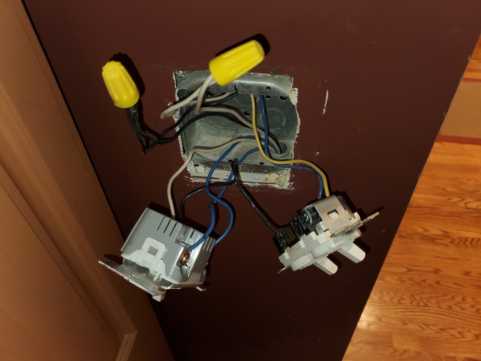
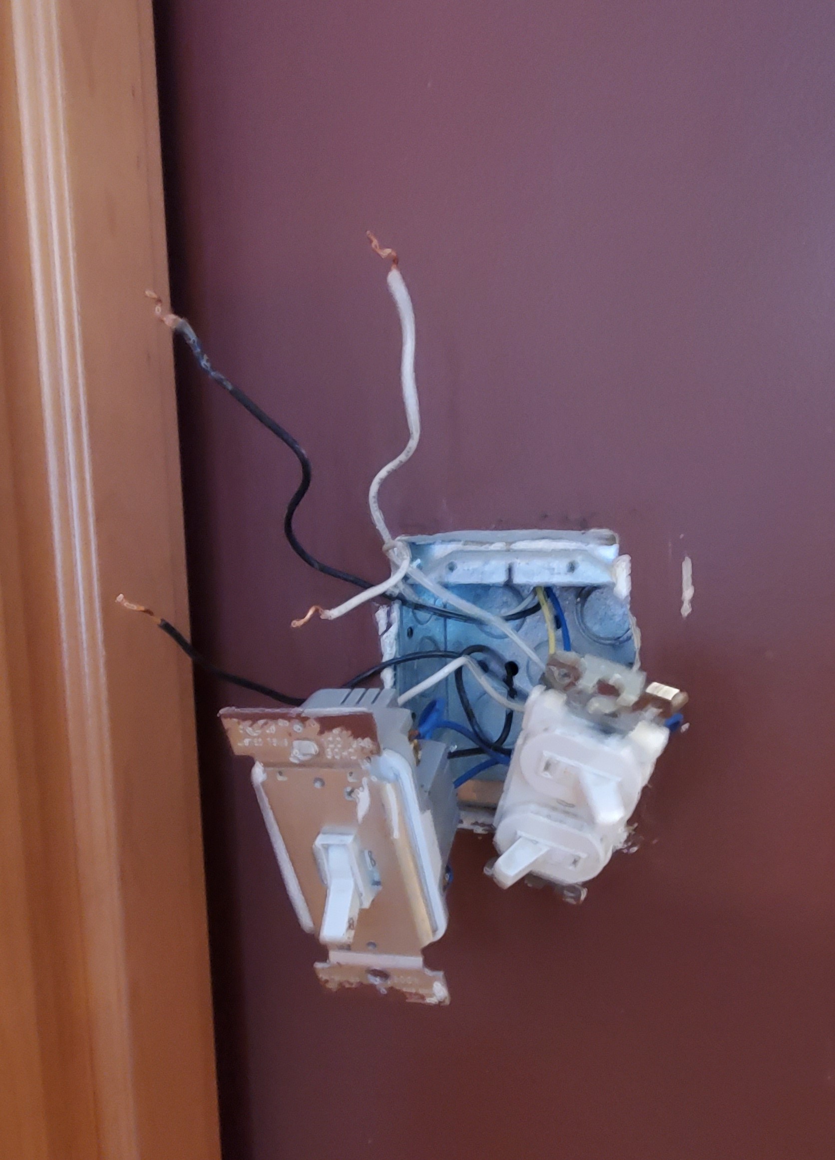
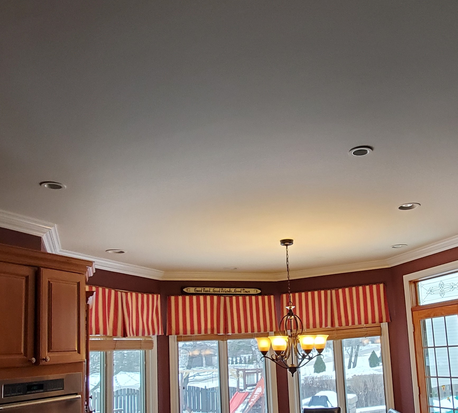
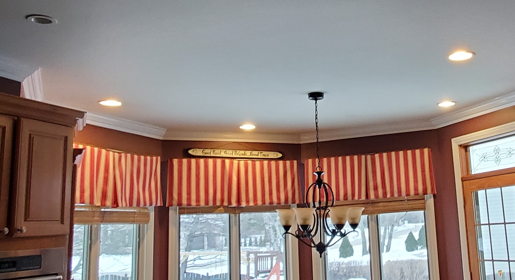
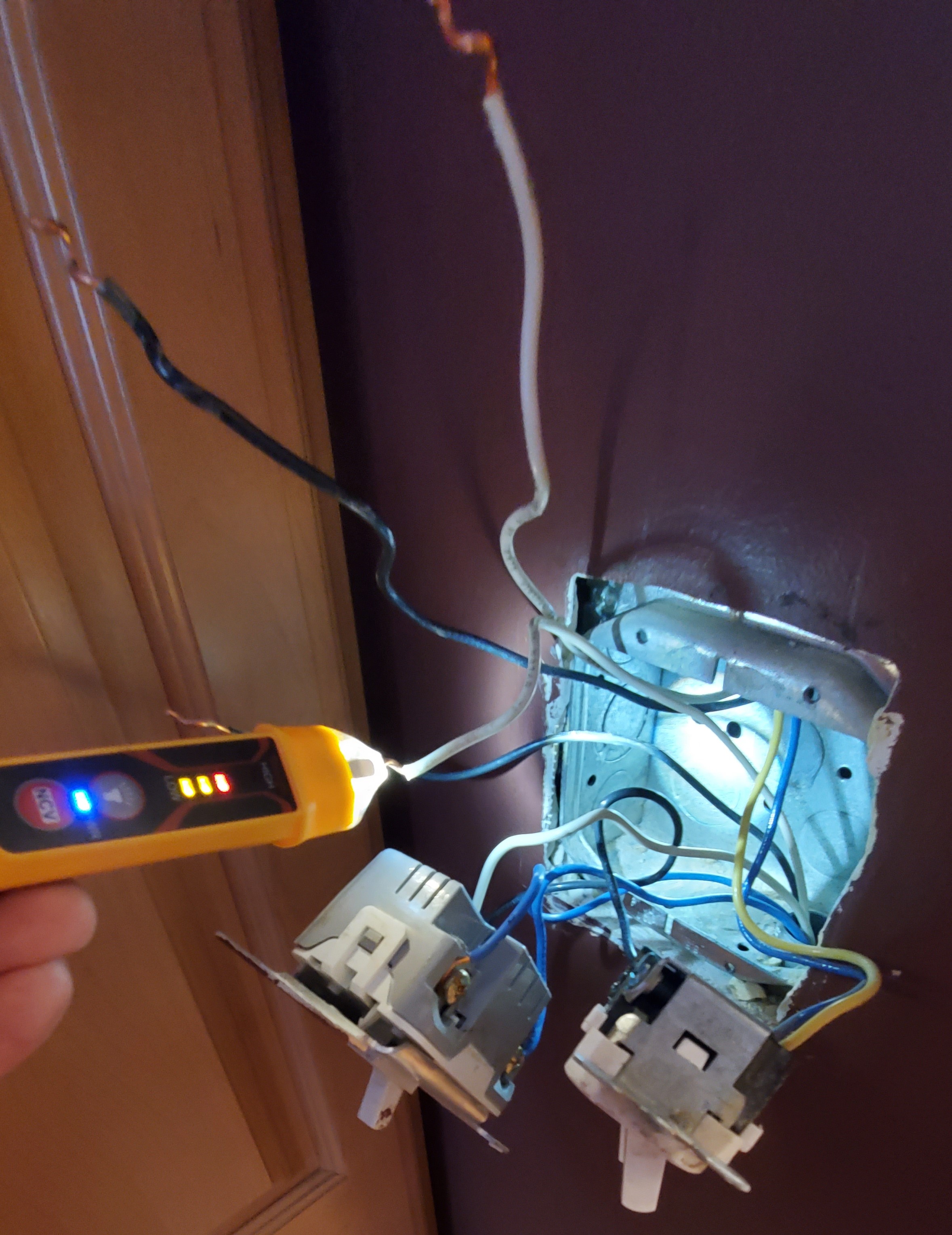
My kitchen has 3 switches. The two horizontal switches control the kitchen lights and a chandelier above our breakfast nook in a single pole setup. The the left is 3 way which I want to change to the inovelli red dimmer. From what it appears the electrician did was take the load wires (yellow kitchen lights & blue chandelier) but then took the black line wire and plugged it with the traveler on my 3 way switch. I assume my 3 way the 2 blue wires are the load/line and the white is the traveler.
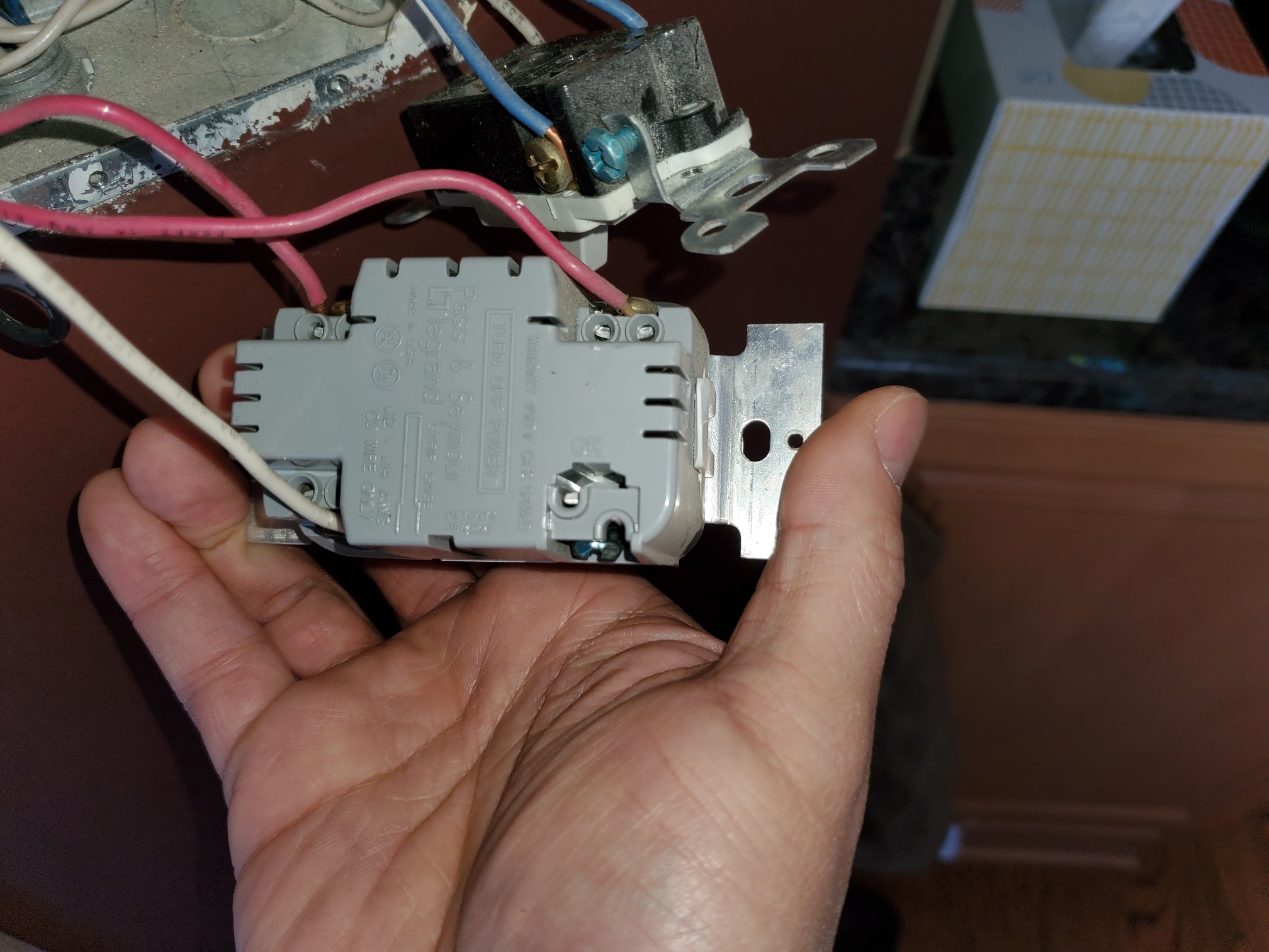
The 2nd picture is the other switch box with the center switch corresponds to the 3 way that I am trying to upgrade. I assume the pink wires at the load/line and the white line is a traveler.
Also to clarify the 3 way switch has a dimmer controller on both sides which I found odd when I bought the house. If one of the switches isn’t in the full off position, the lights remain off and I have to correct on of the switches.
What are these controlling? Single fixture? You are probably going to have to get into the light box to figure out some of this. It’s harder when THHN is involved v Romex.
Temporarily remove white wire from the switch in the top picture. Test for voltage between it and ground (your box) to see if you have a constant 120VAC. Test with the other switch on and off to see if it makes a difference.
Based on the jumper to the other switch, I’m feeling like that white is a hot feed, maybe.
You are right. The 120V is coming from the white wire so I had it wrong in my first post. So with the first pic showing the left switch that I am trying to replace, the white wire with the black wire in the same port is the hot wire. The 2 blue wires are the travelers. The second pic the pink wires are the travelers, the white is the load.
Now with the black wire piggy backing with the white wire, would there be an issue with the inovelli if I did something similar?
Don’t take this wrong, but I got about half of what you said.
So if I understand you correctly, you tested between the white conductor coming into the box from the bottom (connected to the common terminal on the switch) and the box and determined that it is hot, correct?
You referred to the two blue wires and the two pink wires as travelers, and they may be. But those conductors didn’t change color on their own, so did you get into the ceiling box to see if they are connected together so that we know they truly are travelers?
How did you determine that the white wire in the 2nd box is the load? Did you remove it from the switch and test as you did the first white conductor it to make sure it’s not hot? I wouldn’t expect it to be, but you have some funky thing going on with two dimmers and the weird behavior you described, so you need to be sure.
What connections did you find in the light box? If you are correct thus far, you have to figure out how that light is gettng it’s neutral. I see there is another pair of black and whites in the first box. Are they going to the same light? Are they on the same breaker?
Separately, you have a pair of black and white conductors passing through the box. Are they on the same breaker? Do they go to the light?
I know this is a lot of questions, but when you have THHN individual conductors, it’s much more difficult to trace.
I really appreciate you taking the time to help me out.
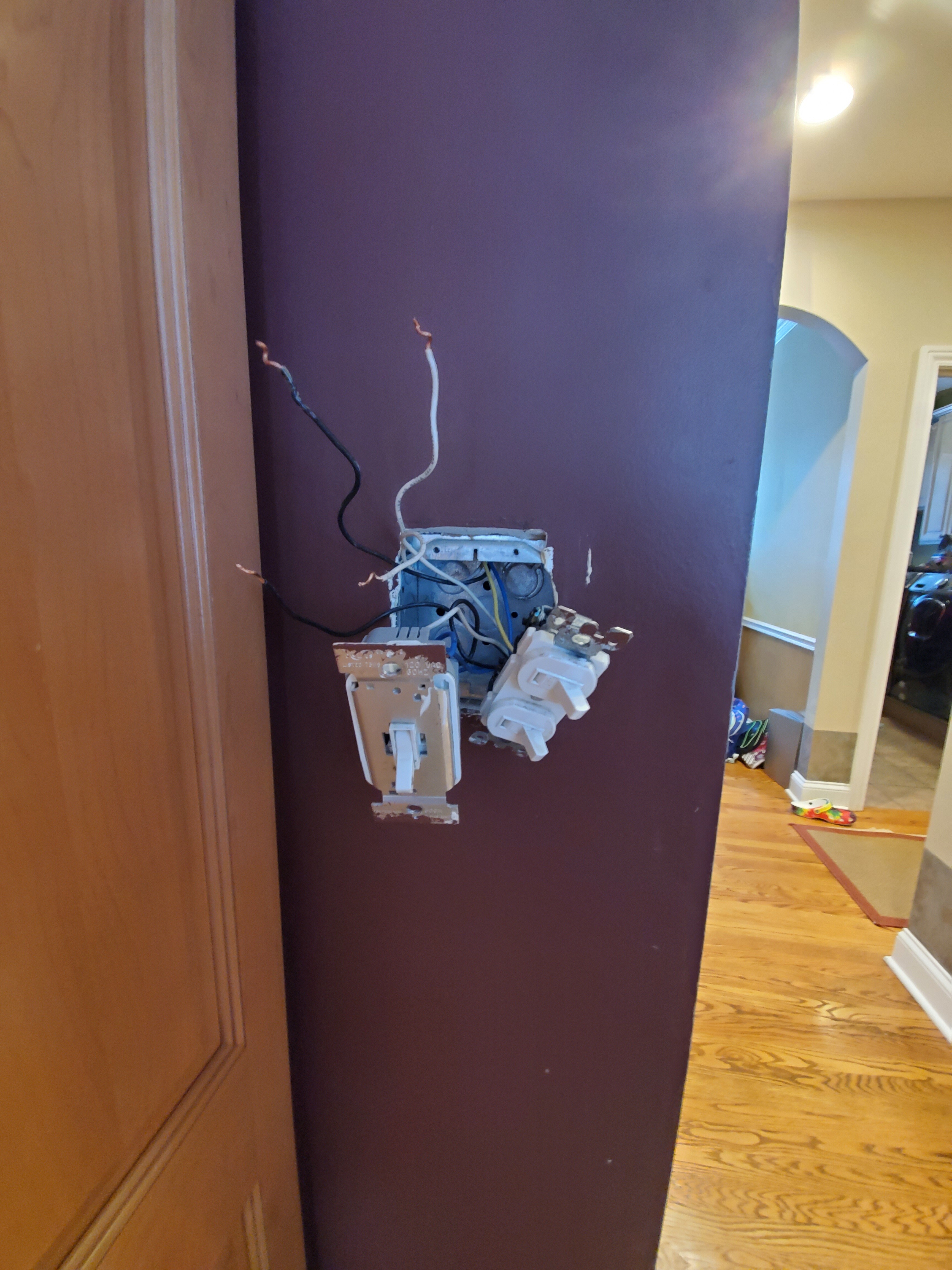
In the first box:
What I did to determine that the white wire was hot was I turned off the circuit breaker, removed all the wires, turned on the circuit breaker, and then tested out the voltage with a voltage meter by touching the black terminal of my voltage meter to the metal box and the white wire to my red terminal which gave a reading of 120. The blue wires gave 0.
For the second box
I turned off the breaker again and reconnected the wires in the first switch. I then went to the second box and disconnected the wires to the second switch. I turned on the circuit breaker and made sure the switch to the first box was on. I then used a voltage pen and it picked up current in the two pink wires and nothing in the white wire.
As for what the heck the original electrician did in between I have no idea. The wires go under the floor versus up into the ceiling. My basement is a finished basement with a smooth ceiling versus tiles so it makes it tough to know what’s going on without cutting into the dry wall.
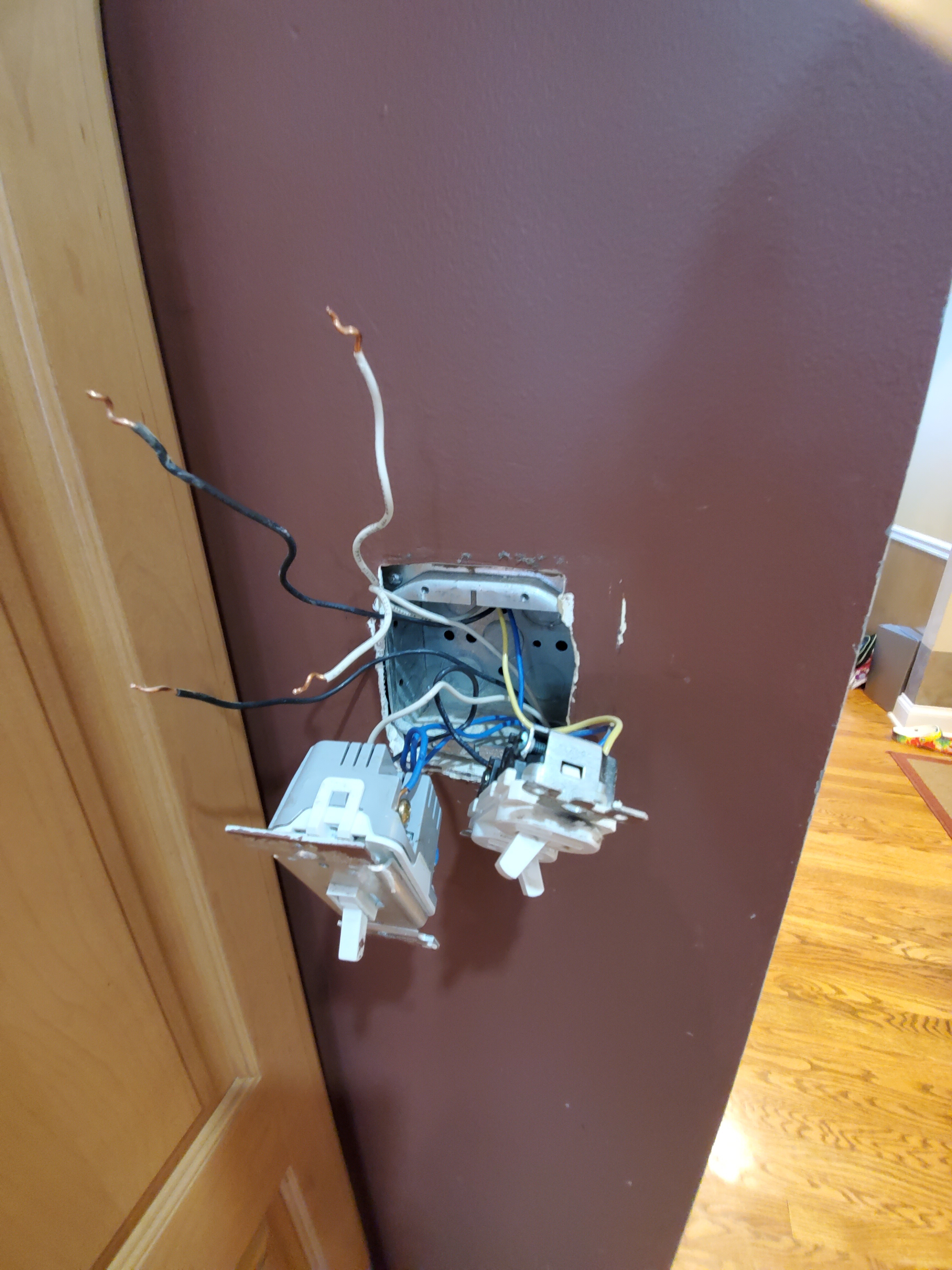
Going back to the first box:
As for the other pair of black and white wires that pass through the box, I am not sure. I didn’t check if they are on the same breaker or not. The blue and yellow wires that go up through the box control the dining chandelier and kitchen cans respectively. I would assume the black and white lines that run through the box complete that circuit, but then why would the original electrician not use that line as the hot.
I take it the next step is turn the breaker off, disconnect the black and white wires, and use the voltage meter. If it is on the same breaker, keep it disconnected and see if either the kitchen cans or dining chandelier work?
I went through your suggestions and started unplugging everything =)
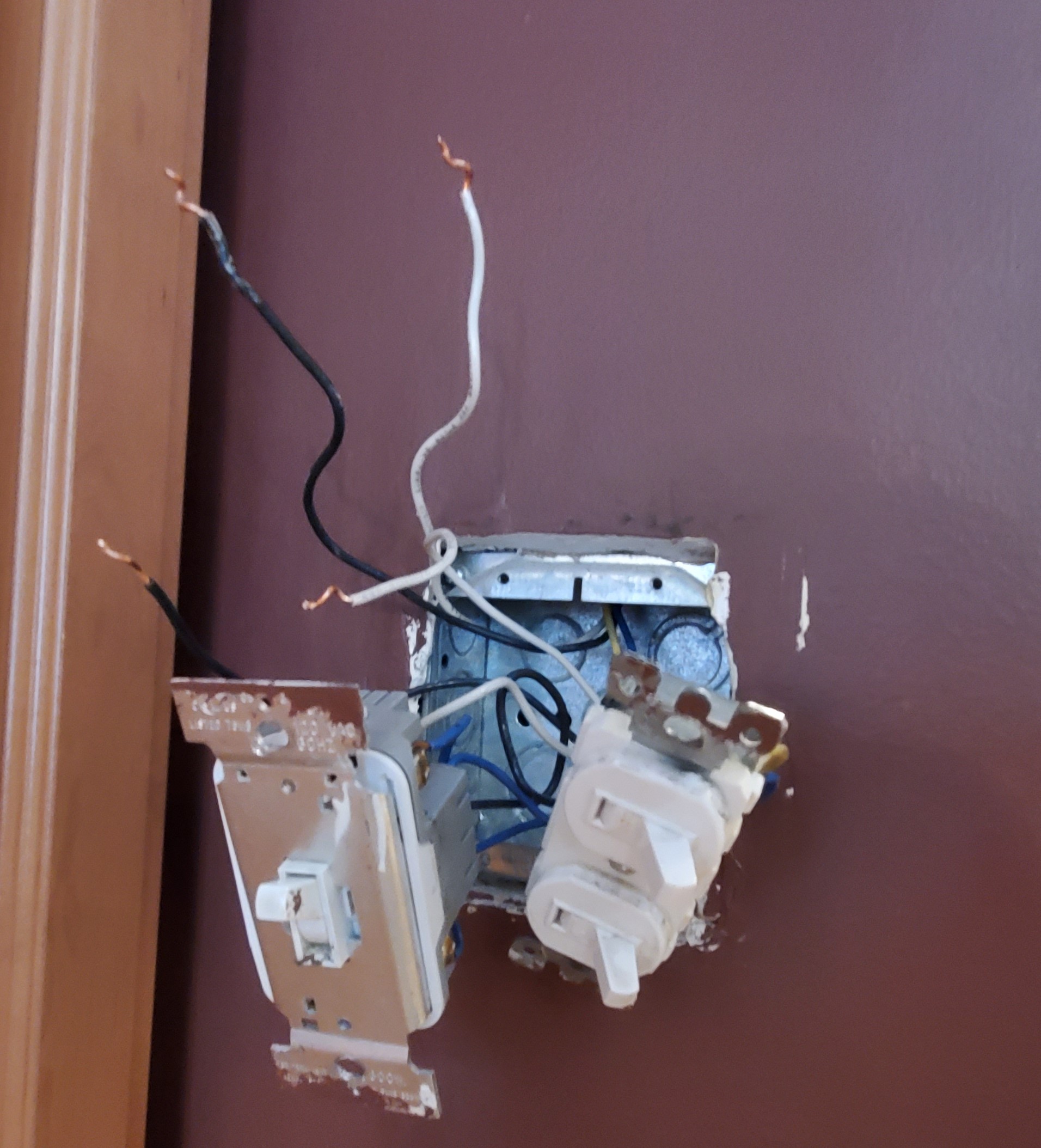
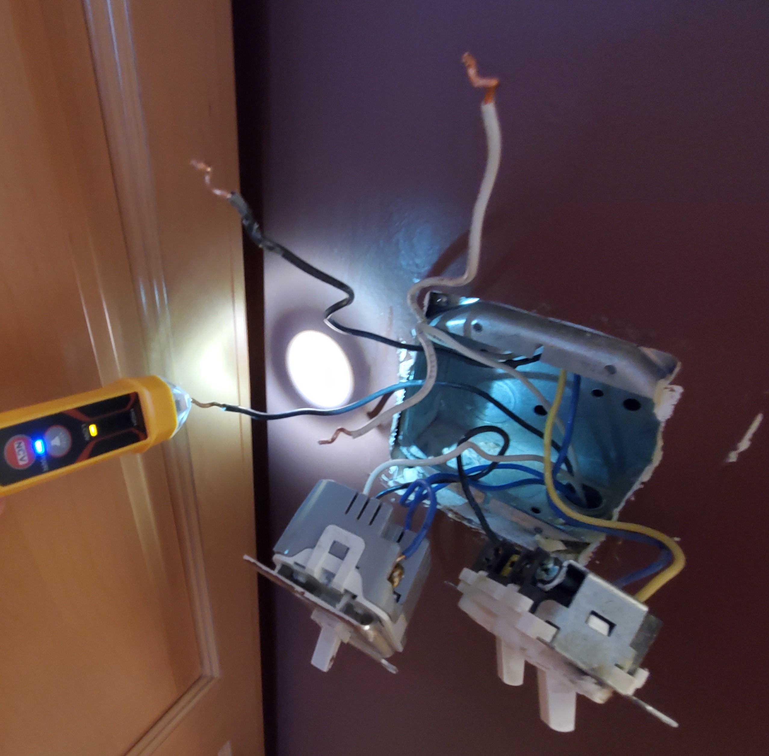
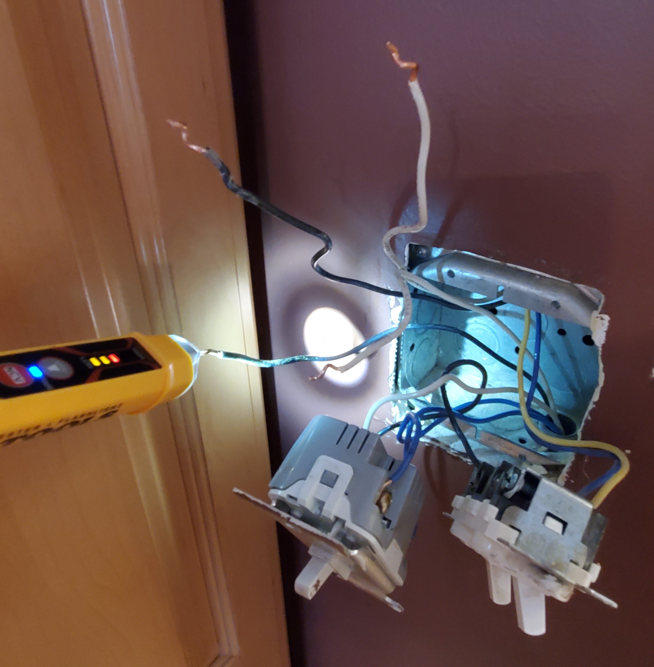
First pic of box 1 with all the lights in the off position and the mystery black and wires disconnected with the lower wires coming from the bottom of the box and the top wires going out the top.
As for voltage checks, it looks like the white bottom wire is a hot wire. While the black wires will not have voltage with the left switch in the off position, but present in the on position.
Unfortunately, you’re not any farther than you were. From what I can tell, your switch leg starts in the first box and maybe goes to the light and then the other switch. I’m only guessing that because the traveler colors “changed”. So you basically have a power to the box without a neutral, so without a full switch leg diagram, I have no suggestion.
As I mentioned before, you’d have to know what is going on in the light box. When you have individuals conductors instead of Romex, the wiring is a bit different and more difficult to diagnose. At this point, you don’t even know how the light get’s its neutral.
I might be best for you to consult with your electrician.
I’m not sure. I took another look at the pics and only see 2 3-way switches. If you are looking at the one switch with the two red conductors on top and the white on the bottom, the empty terminal at the bottom right in the picture is the ground screw (zoom in and you’ll see “GR”), so it’s a three way.
Maybe I missed something? Do you see something different?