Do you have pics of the wiring with the switches provisioned?
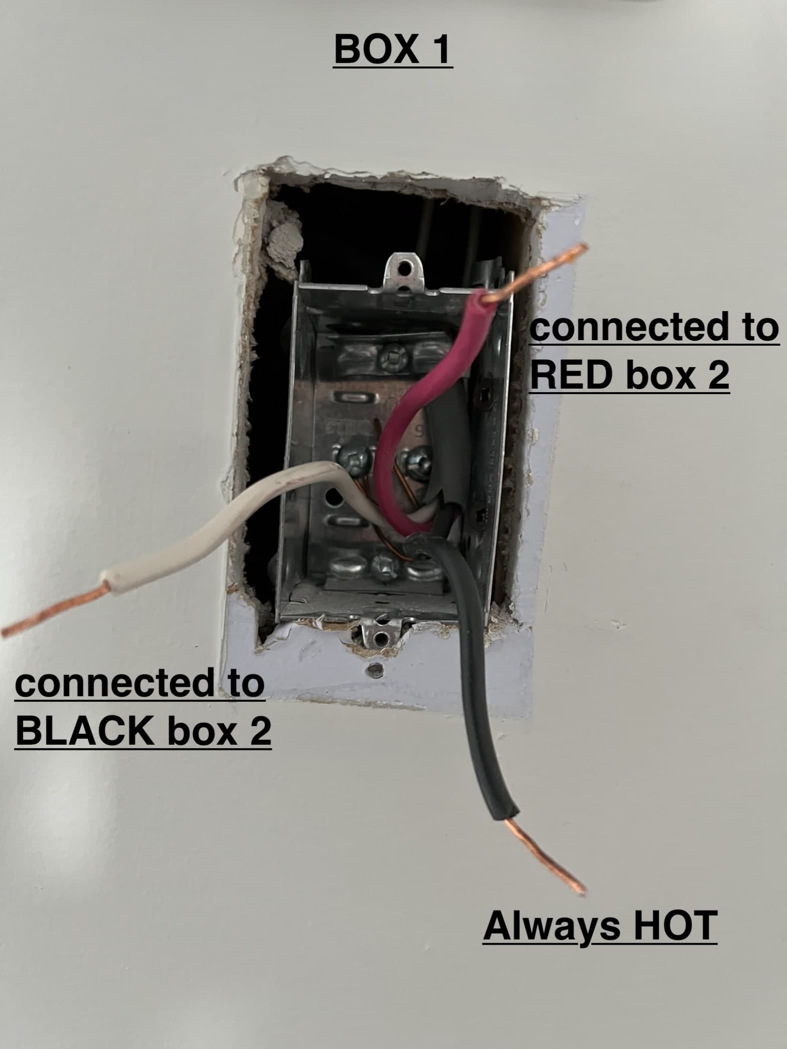
And when you say the black on the 3-wire in Box 1 is always hot, was that test done with the switches removed?
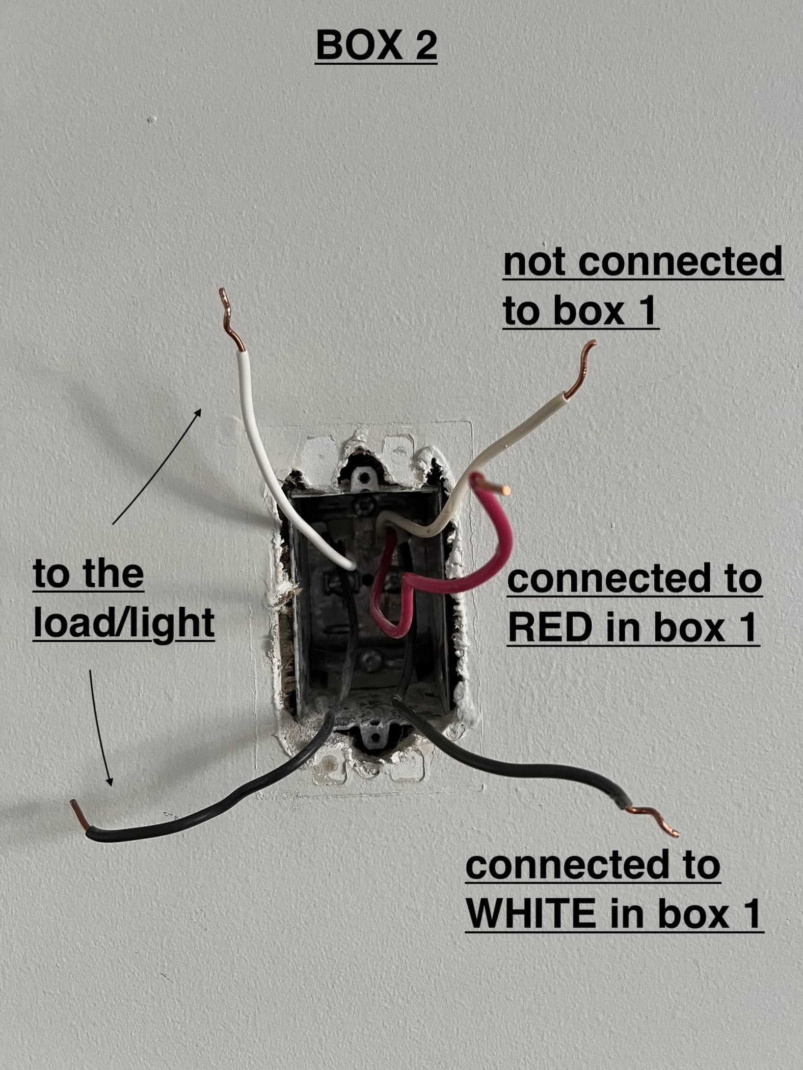
When you determined that the 2-wire in Box 2 goes to the light, did you determine that by actually toning between those conductors and the conductors in the light box?
The conductor schema suggests power to Box 2 with the light in the middle, but the constant hot in Box 1 suggests otherwise.
Unfortunately no it wasn’t the proudest moment when I took it off without taking pictures…
This is correct. After taking off the switch, I flipped the breaker back on and found that is always hot.
(for context the switches control 9 pot lights)
No, I inferred that it goes to the light because the lights would turn on if I feed power to it (by connecting [box 2 white wires] together, [box 2 black wires] together, then [black + white in box 1] – essentially made it a single pole IIUC)
I reached the same conclusion confusion after comparing against many wiring diagrams.
So if you didn’t have the 2-wire in Box 2 I would think power to the light with the two 3-wires going to each box. But that’s not it either because you’ve confirmed the 2-wire goes to the light by powering it.
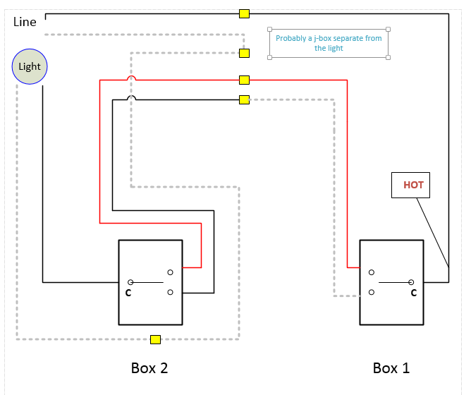
The fact there are mismatches between the connections/colors of the 3-wires in the two boxes suggests that there is a J-Box somewhere that is interconnecting the two 3-wires.
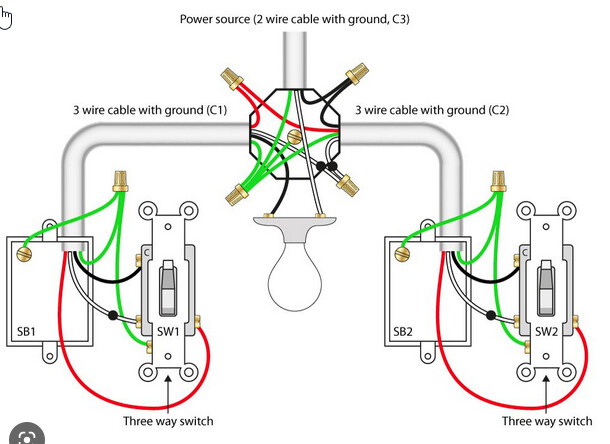
So maybe it’s this. Here is how you do power to the light, non-neutral, with 3-wires going to each box, which is a standard (dated) variant of wiring a 3-way.
But instead of the junction of the two 3-wires at the light box, what if the hot is being fed from a SEPARATE j-box instead of the light. You would still have the same wiring methodology, but it would be a bit different because you have to send the power to the light separately? The fact that you have a single hot (with no neutral) in Box 1 would be consistent with this.
You seem to have a decent understanding of wiring topologies, so hopefully this makes sense. I have no idea if this is exactly what you have, but it sounds good (at least in my mind, lol).
I’ll draw out what I described above as a possible current configuration. You can then test and see if that configuration seems accurate. If it is, I’ll draw a solution from the existing.
My brain says I have to see it in a schematic . . .
After wiring it as such, both aux and the dimmer works as expected, but my lights kept flickering & the dimmer kept buzzing despite in “no neutral” + “3 way aux” + “smart bulb mode” (the load is 9 smart canless light).
I’ve verified the dimmer works with the same canless light in a different location.
I really should have taken a photo of the old switches before I took them off…
Which box do you prefer the Inovelli to be in? Now that you believe my drawing matches what you have, I will take a look at it to see what is possible.
You have a couple options, I think, presuming that the diagram I drew is accurate. Only you can verify that. But if it is, here is what I came up with. These scenarios presume that there will be no re-wiring at the junction box (probably a good presumption at this point),
Inovelli in 2, Aux in 1
This WILL NOT work, as you only have 2 conductors to work with between the two switch boxes. One of those conductors would be used to send the hot from 1 to 2 and the other for the traveler. So you’re short one conductor needed to send the Neutral back to the Aux. (This is presuming that the Inovelli in 2 would be a neutral installation. While there might be an alternative to this if you wired it as a non-neutral, even with a neutral in the box, I shy away from non-neutrals whereever possible.)
Inovelli’s in Both Boxes i.e. No Aux
This WILL work. The downside is more cost for the 2nd switch. You would also have to use associations for the Red series and binding for the Blue series to get the switches to talk to one another. I’m not the guy you want helping if you need guidance with that part. But the wiring portion is straightforward. The two exising conductors between the two switch boxes would be used to ensure a hot and neutral at each box. 2 would be the load box.
Inovelli in 1, Aux in 2
This WILL work with a bit of wiring magic. One of the two conductors between the switches would be used to send the neutral back to 1. The other would be used to send the Load to the Load in 2.
Remove the 3-way
If you don’t need the 3-way, a 2-way with one Inovelli will work in either box.
After discussing with my family, we felt strongly about having scene control at box 2. So I ended up keeping the 3 way and went for the 2 Inovelli’s approach.
I really appreciate you sharing your thought process, this actually helped me ton with understanding the topology & Inovelli’s wiring needs.