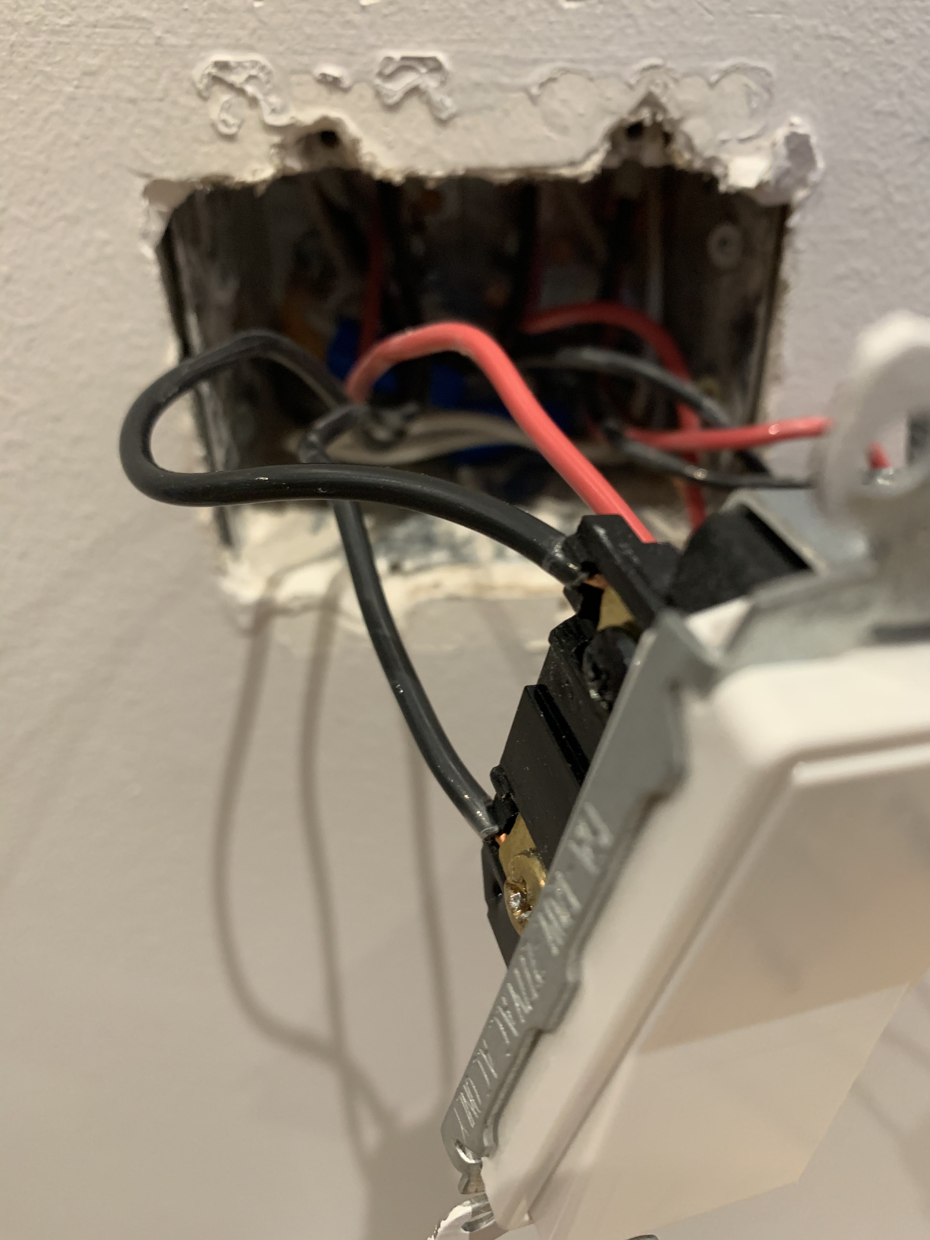
I am trying to figure out what the electrician did here. It is a 3 way - just discovered this. The first picture is my preference to have the inovelli dimmer and the second pic is the light in the corner. The light on left in the second picture is the 2nd switch in the 3way.
Neither light has a neutral connected to it as you can see by the pics. They attached the neutrals together in the box.
I can’t post a second picture so I’ll describe it. Two black wires and one red, similar to the first one. The switch looks to jump the load to another switch in the same box. All neutrals ties together.
You’ll see the neutrals are all connected together in each box.
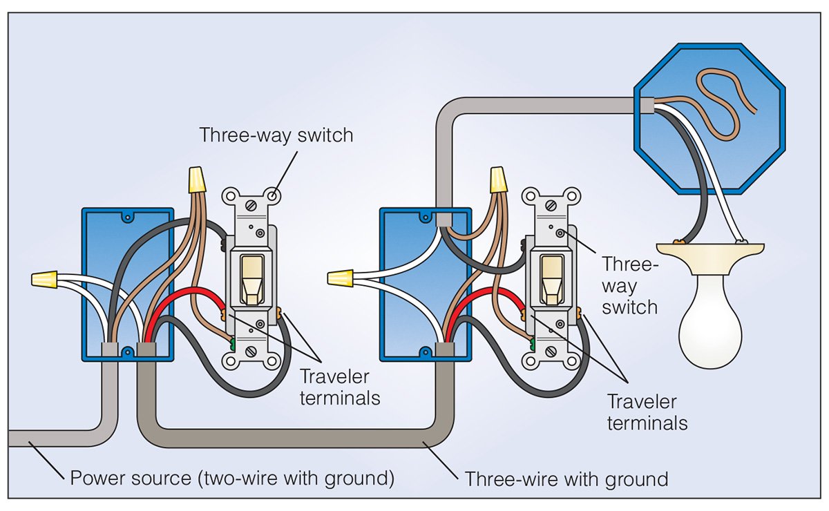
DISCLAIMER: I’m not saying the diagram above is a representation of YOUR actual wiring. You’ve not given enough details for me to make that determination.
I’m just saying that having all neutrals connected together is not generally an indication that something is wrong. Quite the contrary, that’s pretty much a textbook case.
What’s important for you to determine what you can and cannot do, and a plan of attack, is to know where your load (the light) and line (the wire that goes to the breaker panel) are connected.
It appears to me power is coming in the 2nd box. If that is the case, the Dimmer should go in that box.
Before you start you should get a cheap multi meter. You could get by with a “voltage tester”. They can be had on Amazon / Homedepot / etc for about $5 - $15.
Then test the black wire from step 3 below. Verify it has power under all conditions of the current 3-way switches, or disconnect it from the switches and verify it has power. Once we know this is power we can proceed and install the dimmer.
For wiring I would:
add a white wire to the current group of white wires. You may need a larger wire nut.
Connect this white wire to the Inovelli “Neutral”
It doesn’t seem to matter which of the two 3-Way switches in the 2nd picture you are changing to the dimmer the are both wired the same.
Remove the power from the switch you are replacing. The power is the black wire going to the black screw on both the switches.
That black wire goes to the Inovelli “Line”
The black going to the current switch gold screw goes to the Inovelli “Load”
The red going to the current switch gold screw goes to the Inovelli “Traveler”
Note: Others have reported this wiring (although correct) doesn’t always work. It seems to be in the parameter settings. On the Red series parameter 22 should be set to 1.
This is what I think - second pic has the power. I didn’t have a tester with me and thought it counter intuitive to have it in that corner - farthest spot away from the breaker.
Assume for a moment that the power is in the second picture, if I want the inovelli functionality in the first switch what are my choices:
2 inovelli dimmers (one red and one black)
1 dimmer and 1 aux
1 inovelli dimmer and another smart dimmer
Looks like I need an aux but I need the notification on the first switch. Am I missing any options.
I agree power is coming in the 2nd box. Supported by the black wire going to both 3-Way switches. The only way that makes sense is if it’s the power in.
I think your best option is #2 1 x inovelli and 1 x Aux.
Two dimmers would have to go through the hub (can’t have two dimmers powering the same load).