I can not for the life of me understand what’s going on here.
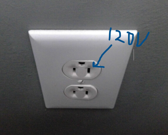
First off, I have 3 way that controls the top half of this outlet.
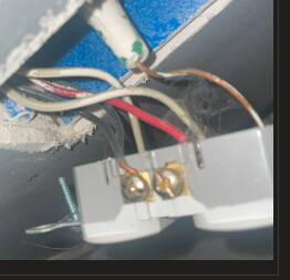
When I unplug all the wires to both switches, the 120V is still hot when measured with to the bottom outlet.
End Goal: I do not care about the 3 way to this outlet, its in a 4 gang setup though, so I intend to replace it with two innovelli switches anyway, that I can control other things in the house with.
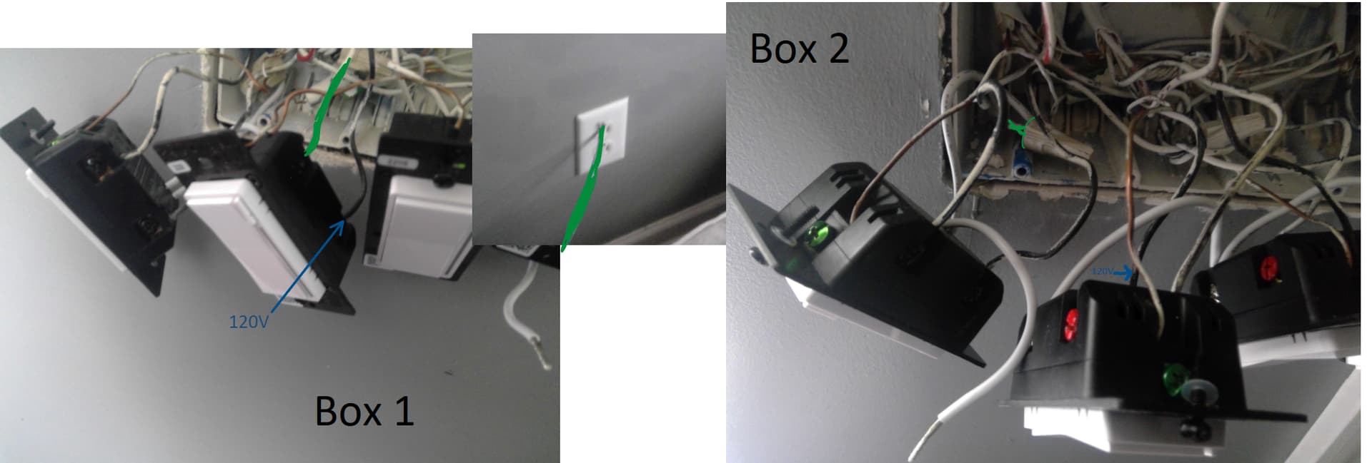
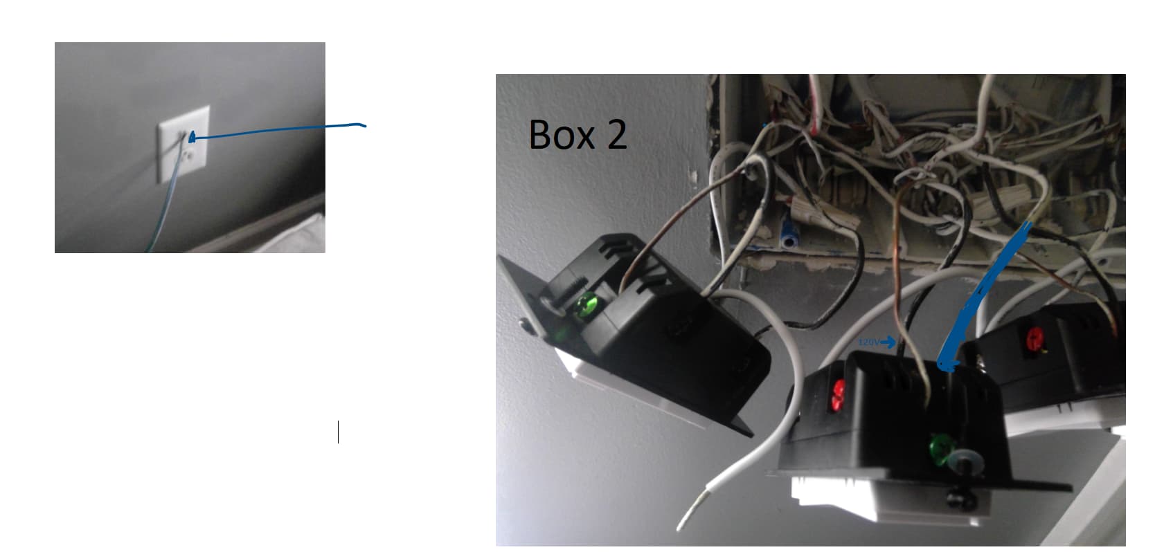
I did some testing to see what wires were connected to what
It seems like the left side of the outlet, is connected to the top of the switch in box 1, and connected to a neutral in box 2?
That is how it’s supposed to work. The hot feed to that receptacle is sent via an UNSWITCHED conductor. So removing conductors from a switch in no way impacts the unswitched outlet.
Do you have any ideas of what my next step should be? Or do I need to provide more information?
I don’t understand, if the power line on the outlet is hardwired to be on, why do the 3 way switches themselves have 120V lines too?
I honestly hate that my house came with this controllable outlet, lol, its giving me so much grief!
I’ve literally spent like 4 hours on it at least at this point, and I just have more questions now lol
There are 2 hot feeds to the receptacle. It’s known as a split receptacle. The tab for the hot feed is broken. So one black screw connects a hot to one outlet and the other black screw connects the switched hot to the other outlet
.
So if I understand correctly, you want to replace the two dumb switchs presently controlling the receptacle with two Inovelli switches which are to be scene controllers only and NOT control the receptacle? Is that correct? Let me know and I’ll suggest how you can proceed.
This will be a bit tough without fully diagnosing your wiring, but this will get you started.
1 - Replace the receptacle with a new receptacle that doesn’t have the hot tab broken. On the hot side, there will presently be both black and red conductors. One of those will be switched and the other constantly hot. If I had to guess, the red is probably the switched hot and the black is probably the constant hot, but there are no guarantees.
You will have to test them to determine which is which. If they’re both presently hot, throw the dumb switches to see which one turns off. Only one will. (Looking at your pictures, you may have removed the dumb switches. Put them back if need be to test. Make sure the switches are working properly before you test.)
Connect the UNSWITCHED hot to the proper side of the new receptacle. Use a wire nut to cap off the SWITCHED hot conductor. Connect the neutral(s) the same as on the old receptacle. Tuck it up and put the receptacle back. You should now have a receptacle with 2 outlets that are constantly hot and UNSWITCHED.
2 - In both boxes, disregarding what you are putting in to replace the dumb switches, do you have properly functioning Inovelli NEUTRAL INSTALLATION switches? In other words, do you have a properly functioning Inovelli switch that is wired with a hot and a neutral in each box?
1 - Replace the receptacle with a new receptacle that doesn’t have the hot tab broken.
What do you mean when you say the hot tab broken receptacle?
Did I break something when pulling the original switches out?
Or do you mean my wall power outlet is broken?
I opened it up and I can replace it with a new one from Lowes but I have a hunch that’s not what you mean.
I’m probably going down the wrong path I’m guessing.
In regard to question two.
do you have properly functioning Inovelli NEUTRAL INSTALLATION switches?
I have one properly installed in Box 1 that is configured to be a dimmer.
Haven’t gotten that far with box 2 yet.
I can daisy chain the neutral right? Do I still need a line or load?
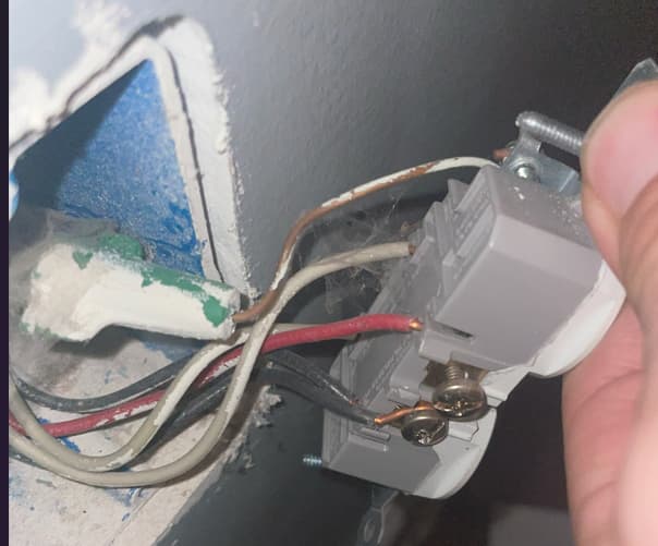
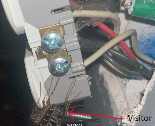
This is the tab being referred to… It comes intact on a NIB receptable and is typically left that way, but it can be snapped off with a needle-nose pliers for split-receptacle wiring (as yours is now ), which is fairly common to have in older construction homes.
Yeah, my side with black wires doesn’t have the tab
The side with white wires does have it
There also is a visitor too who came out of the wall I’m guessing lol.
So only the top part of the outlet is 3 way, is that why there isn’t a receptable on the other side?
So to make it non 3 way, I can put a receptacle on there?
See what Hydro just posted, but TBH, I explained split receptacles above.
I don’t mean this in a bad way, but the wrong path you may be going down is trying to do this yourself. I recommend that you seek the help of a licensed electrician. Unfortunately, a certain level of electrical knowledge is necessary to do this stuff safely.
Thanks Bry, I appreciate the honesty. However I am very capable. I’m just kidding lol!
I will take your advice and get an electrician.
I’m a software engineer by trade, so I was hoping I could figure this out, I did take some circuits classes and stuff, but yeah, clearly I don’t know what I’m getting in to.
I like DIY stuff, but yeah, for this one I may be best off throwing in the towel.
Thank you guys for trying to help me!
I’ll post back with how it goes!