I need some help with set this up with a Red Dimmer
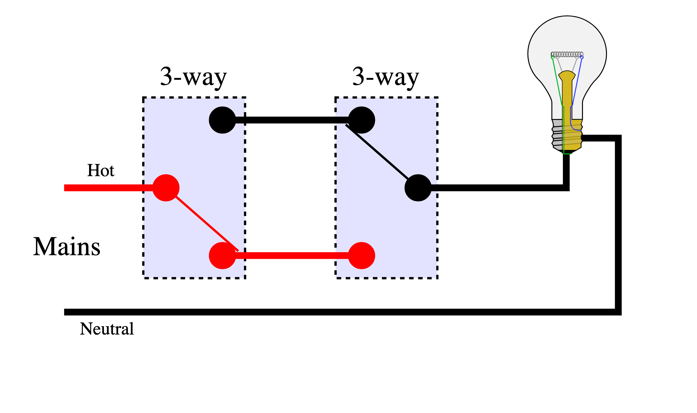
I have a knob and tube setup like this the neutral line does not go to any of the switches and returns directly to the box and the hot line comes straight from the box:
I need some help with set this up with a Red Dimmer
I have a knob and tube setup like this the neutral line does not go to any of the switches and returns directly to the box and the hot line comes straight from the box:
I have done this at my house with the caseta line where a remote replaced the second switch (right switch).
In that case I bypassed the right switch (tying one of the travelers to the bulb, and just capped the other traveler with a wire nut. Then connected the load on switch one to the connected traveler.
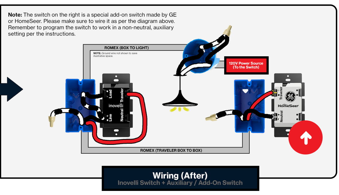
If you are planning to use an aux switch then I think the unused traveler can be connected in that box to the aux port on the red series.
I’m not sure if you can get this going or not, but your drawing isn’t correct.
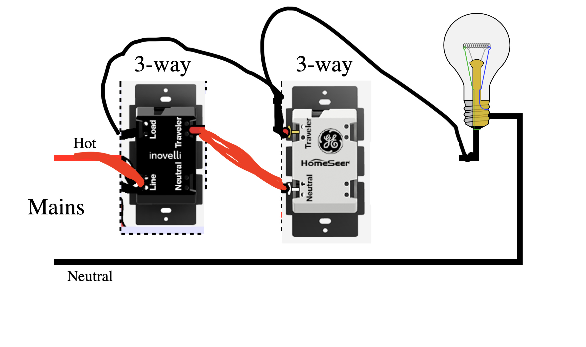
I can tell you how you wire a non-neutral with an Aux and you can go from there.
There needs to be two conductors between the two switches. The incoming hot conductor gets wired to the Line on the Inovelli. Using the 2nd backstab hole, wire one of the two connectors going to the Aux, where it gets connected to the Neutral terminal. The other wire going between the two switches goes between the Traveler on the Inovelli and the Traveler on the Aux.
Lastly, the conductor going to the light needs to be connected to the Load on the Inovelli. So the Inovelli is going to have to be in the box with that conductor.
Take a look at page 12 here:
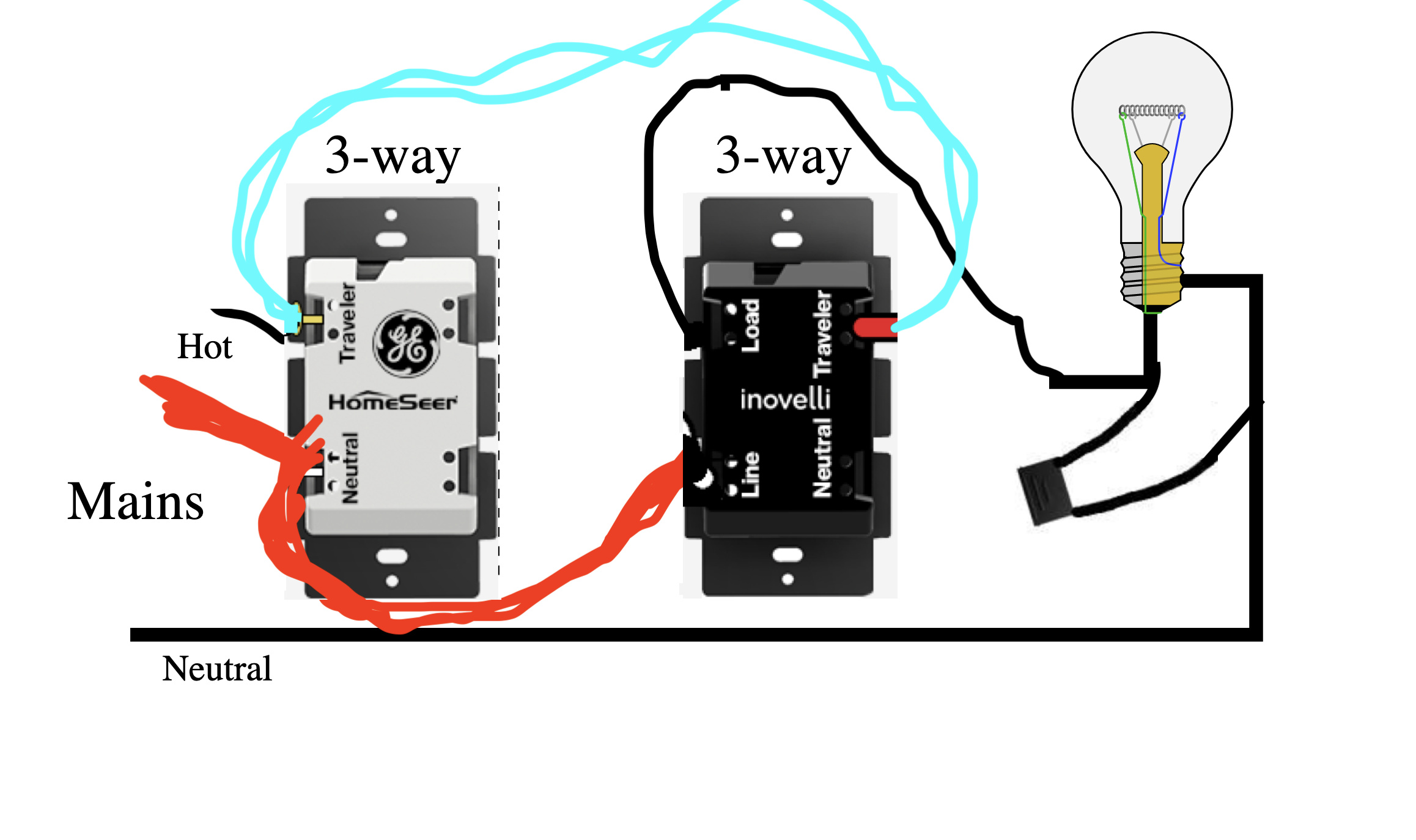
@Bry Thank you for the advice. Another try at this diagram. Does this look correct?
The diagram I posted is correct. It follows the same principal of the diagram you posted but works in my exact circumstance.