The box with hot / power has two different switched outlets in it - all powered by one circuit from the panel. One circuit is a simple two way (and already running a LZW30-SN) the other is the 3-way.
This photo shows the box (2-way install in progress). Switch on left is 2-way, switch on right is 3-way.
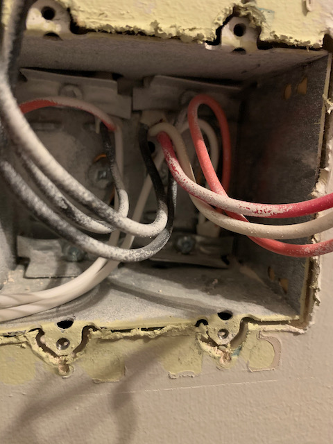
This photo shows the wires in the box. Left most three conductor is hot on black and red is used to switch the split plug on the 2-way. I believe this also provides line for both switches. The middle three conductor is tied to the 3-way dumb switch (see next photo). I believe the right-most three conductor runs to the outlet - black being the constant on and red being switched.
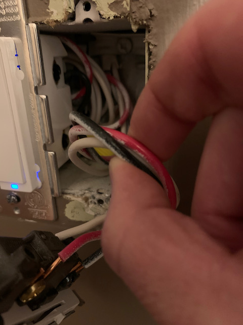
This photo shows the dumb switch on the other end of the 3-way circuit. There is another circuit in here (with Zooz switches attached) that control lights. The three conductor attached to this switch is not connect to any of the other wires in this box (it only goes back to the outlets or the box pictured above.
Just working off your diagram and did not look at your pics.
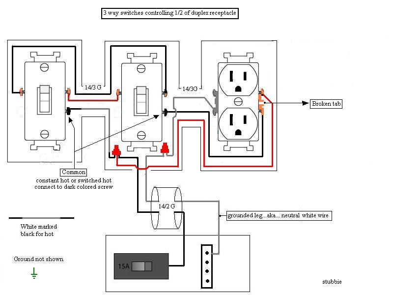
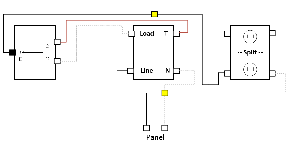
While it may look confusing at first, it’s a bit easier to understand if you disregard the constant hot feed for the unswitched half of the receptacle. I took it out of your diagram so it’s easier to see:
So your hot starts in the left box and gets switched over the two travelers to the right box and goes out the common terminal to the receptacle. The only thing that’s different from what you usually see is that the neutral doesn’t start in the left box.
So while I think it’s possible you can do this with a dumb switch, I can’t quite visualize it at this point. It would take a lot of rewiring at the switches.
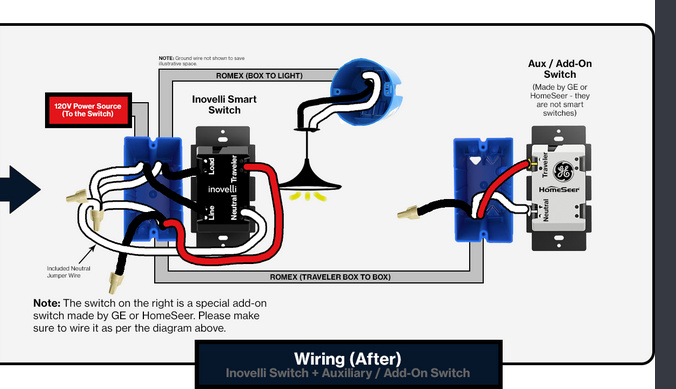
The easier solution might be to do this with an Aux instead of a dumb switch, as you only need two conductors between the two switches. I’m not sure if/how an Aux does with a switched receptacle. Perhaps @harjms can comment here.
So what I’m thinking is that using an Aux you have a Line/Load in the same box (which in your case is the right switch box):
Speaking theoretically, the Inovelli would go in the right switch box. You have a hot and a neutral there. Leave the neutral to the receptacle as is, pigtailing for the switch. The black presently going to the switched receptacle gets connected to the Load on the Inovelli.
Now you just need to send a neutral and a traveler to the Aux. Use 2 of the 3 conductors on the 3-wire between the switches.
Make sure you have lots of pics and labels if/before you start taking this apart.
Thank you @Bry! I’d really like to keep the dumb switch if I can … are we effectively looking at rewiring to a different method of wiring a 3-way to achieve that? Curious if @harjms has thoughts per your suggestion.
The other thing I could do (I think?) is defeat the 3-way and make it a simple 2-way by capping off the three conductor to the remote switch, right? That’s probably least desirable as the remote switch is the one that gets physically used exclusively.
Honestly - I’d love to ask the electrician that wired this house or the original homeowner if they picked switch locations what they were thinking. The two switches for this room are located in the front entrance and the one remote switch (that we use and only turns on 1/2 the room) is located on the other side of the house by the entrance to this room.
Let me see what I can come up with dumb switch wise. I’ll have to draw it out as that one is a bit tough to “see” without it. @harjms might see it. We’ll get our heads together.
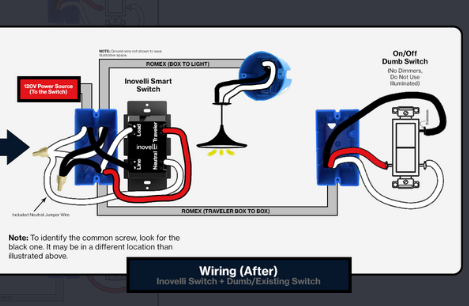
@harjms - just read back through your reply. I’d like to put the Inovelli in the “right side” of the diagram. Dumb switch left, Inovelli switch right, then outlet (in the diagram).
I just sent this to James for him to double-check. But in the meantime, take a look at this. I left the constant hot red to the receptacle out of the drawing, but that conductor is still there on the 3-wire to the receptacle so you won’t lose that.
This is basically a Line/Load same box neutral installation, as in Inovelli’s drawing below. It was too easy, so double-check to insure I didn’t miss anything.
Looks great @Bry. This should work as presented. Just hopefully you don’t have any dumb switch issues. Make sure you configure the parameters right. You may have to force the switch type.
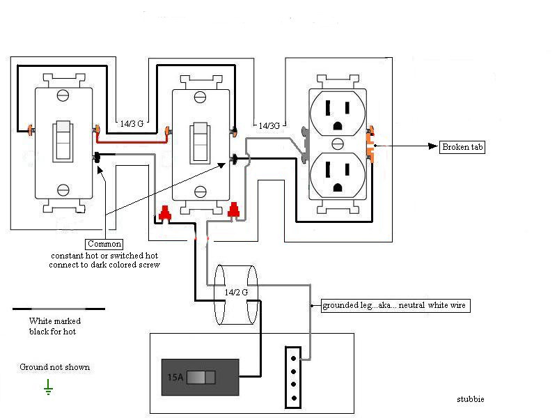
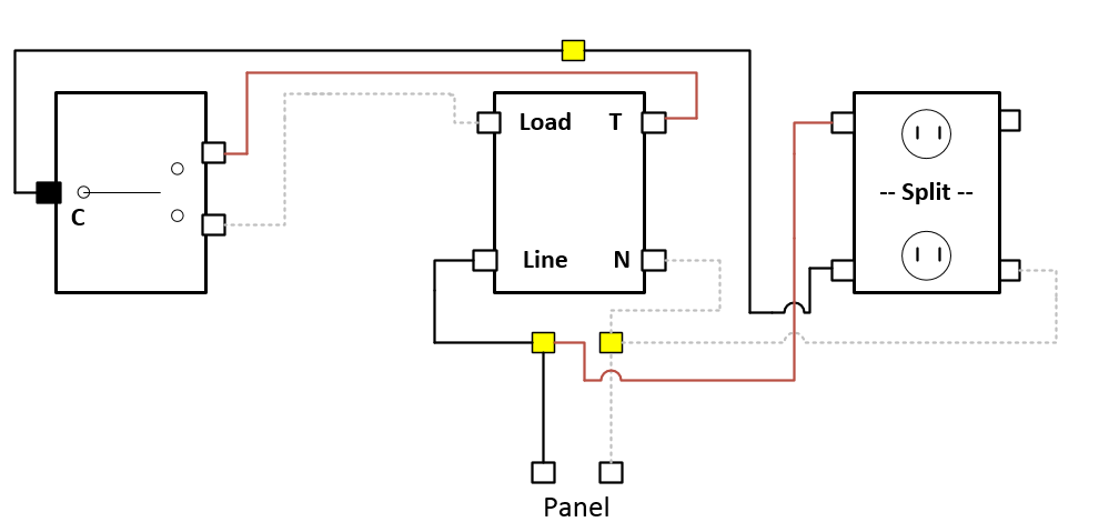
Here is with the constant hot red from the 3-wire to the receptacle added back in. Just for ease of drawing, the constant is on the top, although yours is opposite.
Thank you @Bry and @harjms! I was having some renovations done on the house so I couldn’t get to this for a little while - went over your diagram and my wiring again a few times and wired it all up working on the first try!