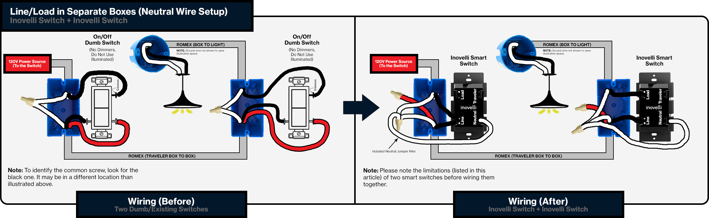
I am struggling to get both switches in a 3 way configuration working as smart switches. I am going off of this wiring diagram as the wires in the previous picture match my setup:
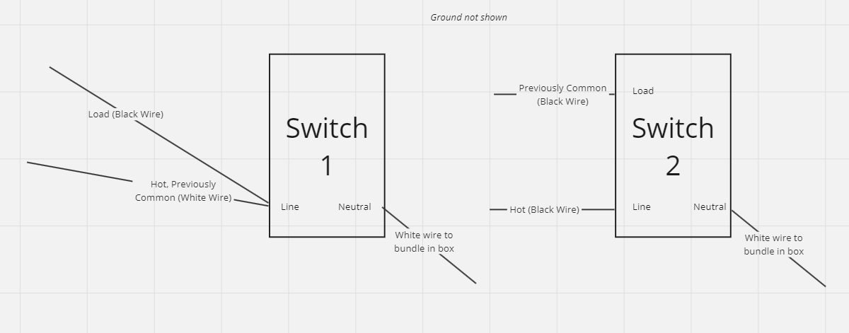
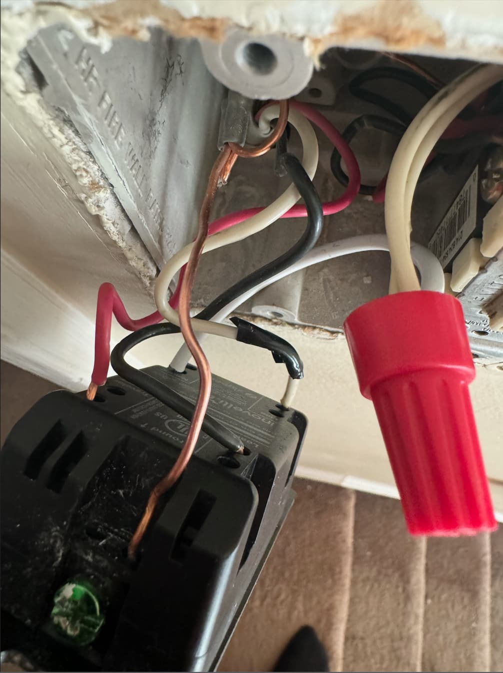
Here is how I wired my switches where I have labled which wire was the common wire from the “before” pictures. These wires were attached to black screws in my old switches:
I tested each wire and saw that the white common wire was hot and one of the black common wires was hot when nothing was connected which was why I configured them they way I did.
The problem I am running into is that Switch 1 just won’t turn on, switch 2 controls the light and works fine.
Just tried wiring each one like a single pole w/ neutral and zigbee binding everything together (Lights+Switches in one group bound to endpoint 2 on each switch) and it works better than before but not quite there. I get some flickering and weird dimming behavior but the lights ultimately turn on and off with both switches… Do I need to just purchase AUX switches or use dumb switches for one of them? Not sure why my secondary switch had hot wires when nothing was connected to the primary switch which didn’t seem to be the case in most diagrams.
The flickering you’re seeing could actually be some incompatibility with the bulbs or fixture. It’s not uncommon for LED’s, especially the cheap ones, the flicker when connected to smart switches. If you’ve got some other bulbs around the house you could try testing with those.
There is some weird stuff going on with the Switch 2. It can turn off the bulbs but they turn right back on. The local protection setting for switch 2 does not do anything, it still turns off the lights and they turn right back on after some flickering. Switch 1 local protection works and it is behaving properly, even dimming the bulbs works great. Also if I disable smart bulb mode on Switch 2 both switches lose power and reboot once I re-enable it.
This sounds like a wiring issue. It sounds like your line connection to switch 1 is running through switch 2’s load connection. You’ll want both switches connected directly to line instead.
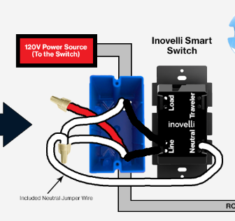
Only 1 switch should have a load connected to it. Both switches have constant power and neutral. Your old traveler wire (likely red) capped on both sides.
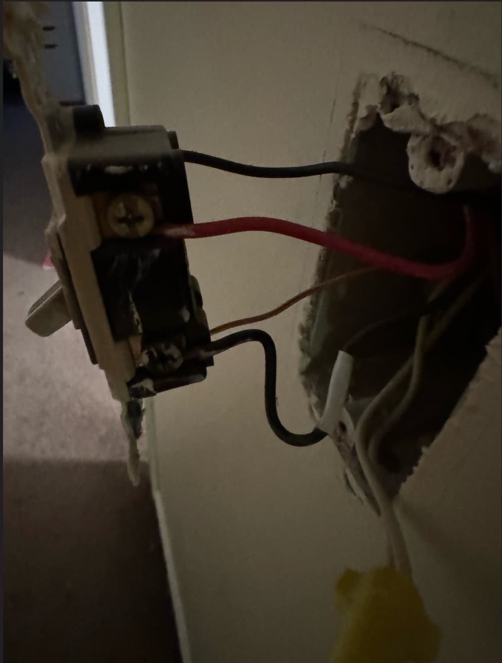
Thanks, my travelers are capped as I followed the “Line/Load in Separate Boxes (Neutral Wire Setup)” pictured above until I tried the experiment of wiring each switch like a single pole. The first resulted in only Switch 2 turning on (from the picture above).
As an experiment I tried to connect both the line and the load to the line of each switch, leaving the red wire capped and still keeping the neutral and ground wired as they were. This resulted in the light turning on but both switches off. Shouldn’t the switches be on in this scenario but unable to turn the light on or off without a zigbee binding or some other automation to control the light? I can see power going into each switch, I havn’t measured it but I bought a Multimeter on my way home tonight…
Unless I’m missing something this feels like there is something wrong with the neutral and the switch can only work if the circuit is completed by having a line and a load, like a non-neutral setup. I am able to use one switch fine like this but it obviously doesn’t work for the second one, though even with both 100% unplugged and the wires separated the downstream switch somehow has hot wires. I guess I can double down and try an AUX switch for the second one.
Last data point before I call it a night, up for any suggestions though and can try them in the morning. Once I got Switch 1 working fine in a single pole neutral questionable configuration I decided to swap it with Switch 2 and see what happened. Switch 2 ended up having the same issues I was seeing when I had both switches in a single pole configuration. Since those wires are hot even with nothing connected I might try a different switch there (I’ve got like 16 of these, not off to a good start) or just order an Aux since I’ll be down a switch since this one is having some issues. I ended up buying refurbished switches due to the lead time on the new ones.
Recap:
Switch 1 which is where power comes into this circuit does not power on with configured as the wiring diagram for “Line/Load in Separate Boxes (Neutral Wire Setup)”:
However the light still gets power so possibly an issue with the switches neutral but I’m not sure how to confirm this (all these boxes have neutral for multiple light fixtures which all have switches in the box).
Switch 2’s common wire is hot even if Switch 1’s Line, Load, and Traveler are capped
Switch 1 & 2 both worked in a single pole neutral configuration but Switch 2 had issues dimming and turning lights off.
Switch 1 works fine in a single pole configuration w/ neutral though it’s hard to tell if the neutral gets used. When swapping it with Switch 2 the same symptoms occurred as when both switches were in a single pole configuration.
Local protection enabled does not prevent switch 1 from turning the light on or off when it is in a single pole configuration
6 (new). The working single pole config’d Switch 1’s LEDs blink randomly when the lights are off. It’s not very frequent but it is odd behavior.
I can provide pictures or a better diagram if necessary but hopefully the one above make some sense as to what wires are there. I labeled which wires were in the black common screws from the dumb switches.
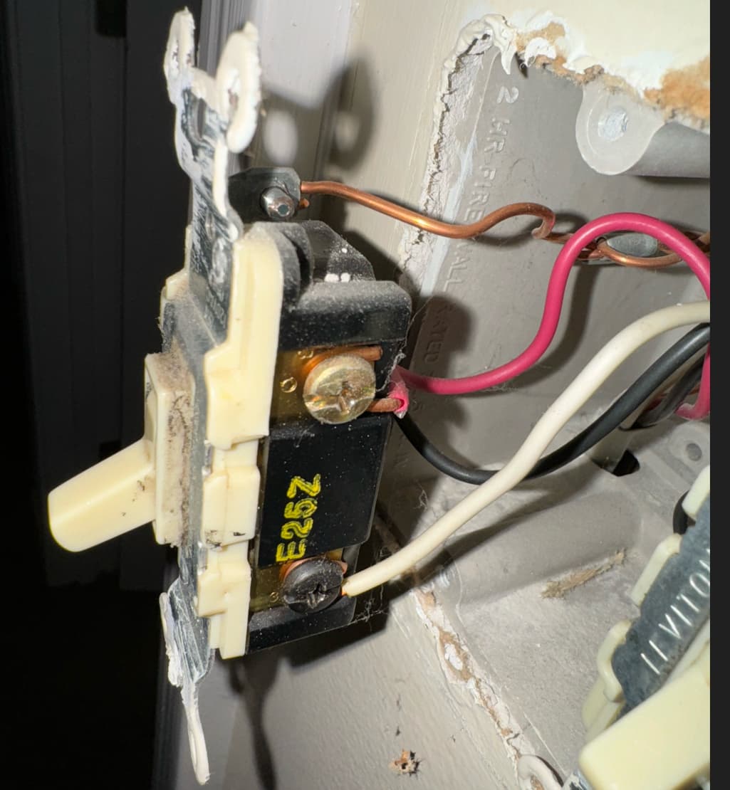
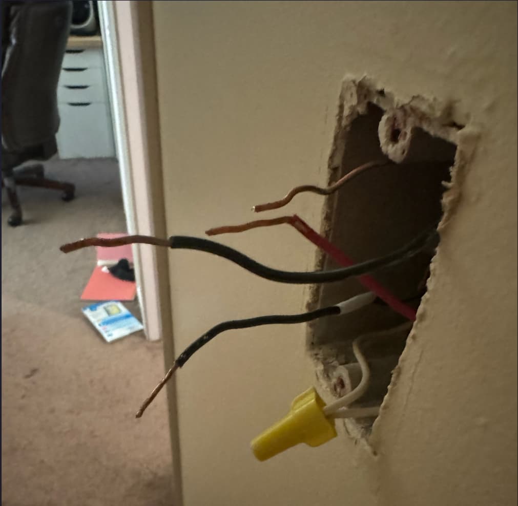
Some pictures would be helpful. If you can clearly pull out both switches and take pictures showing all of the different wires in the boxes and label those that may be helpful.
I think you’ll need to use a voltmeter and track down which wires are actually hot and if you have neutrals in any of the switch boxes. The setup you are trying will need a hot and neutral in both boxes and one box will have the load.
Got it. Sorry for the delay, busy week at work. I got an AUX switch and tried that in the neutral and non neutral wiring schematics but neither worked. Either the main switch wasn’t powered on (non neutral) or the AUX switch did nothing (Neutral). I made sure to see the white flash after holding up and pressing config 5 times on the smart switch so it was set right. I also tried manually configuring the smart switch like this:
But it did not make a difference. I’m confused about this config as it sounds like it’s intended for the AUX switch but the AUX switch wouldn’t be paired to Z2M.
I really appreciate the help. I hope to replace the majority of my switches with smart ones and I’d like to use inovelli’s since they are so friendly with HA and I like the LEDs. Right now we don’t use our switches since all the bulbs are smart, it’ll be nice to have them back.
If I have some time tomorrow I’ll take some measurements of what is sent to the wires for the secondary switch. The first smart switch I tried to use there is still acting up and I can swap it out for another one and things work fine so I think a lot of my troubleshooting has been clouded by a faulty switch. However I don’t understand why I couldn’t get the AUX switch working and I hope I can get better picture measuring the output to each wire as I toggle the main switch.
I also don’t quite grasp how aux switches work since I haven’t seen one in action or found much in depth docs about them. What I read makes me believe you just need to configure this parameter in the smart switch:
OK, I’m still seeing a traveler wire hooked up there, and a white wire used to cary line voltage. None of this follows the diagram you were following in the first post.
Step 1: Find your line wire. Use a meter and read for voltage.
Step 2: Find the 3 wire (black/white/red) that goes from 1 box to the next box.
Step 3: Cap off the red wire at both ends
Step 4: Your line wire with power goes to Line on 1 switch along with the black wire from step 2, then in the other box that black wire goes to Line on the other switch.
Step 5: Bundle and do the same with your neutral wires
Step 6: Your load wire up to the light goes to the load terminal of whichever box it’s in and add the neutral from that to your neutral bundle.
Both switches need power and neutral. 1 switch will have a load connected, the other will not. No traveler wires are used.
EDIT: Title says 2 smart blue switches, but then a post later on says AUX switch. The above will work based on the title, however if you’ve got an Aux and not 2 smart blue switches this will not work. So what are we wiring up here?