Disclaimer: I’m stupid. I’m planning to hire an electrician and return to this thread with the solution later since I don’t believe this is simple, and I haven’t seen a matching example of the ~dozen posts I’ve checked so far. Regardless of feedback, I’ll post back with a solution once I hire somebody to tell me I’m stupid and fix my stupid.
There’s an assumption in all of the wiring schematics for the 3-way with neutral wiring that wherever the live/line/hot wire exists, there’s going to be some additional spare twist-on wire nuts for handling the proper configuration for the line, load, neutral, and traveler connections for the Inovelli switch. In my case, it seems like my line is coming in to a switch that doesn’t have additional spare twist-on wire nuts.
My goal was to try to figure out which switch has my line/live/hot wire. To do this, I’m going to leave my breaker on so I have power going to the switches, but I’m going to keep the switches in an open circuit configuration so I know the load line will be 0v. If there’s a better way to handle this or reverse engineer this stuff please LMK.
Based on the results of trying to figure out the preexisting schematics of my two dumb switches in an open circuit configuration with my multimeter, I’m really confused. From what I infer, the red wire going into the common in the switch1-open.png attachment is the live wire.
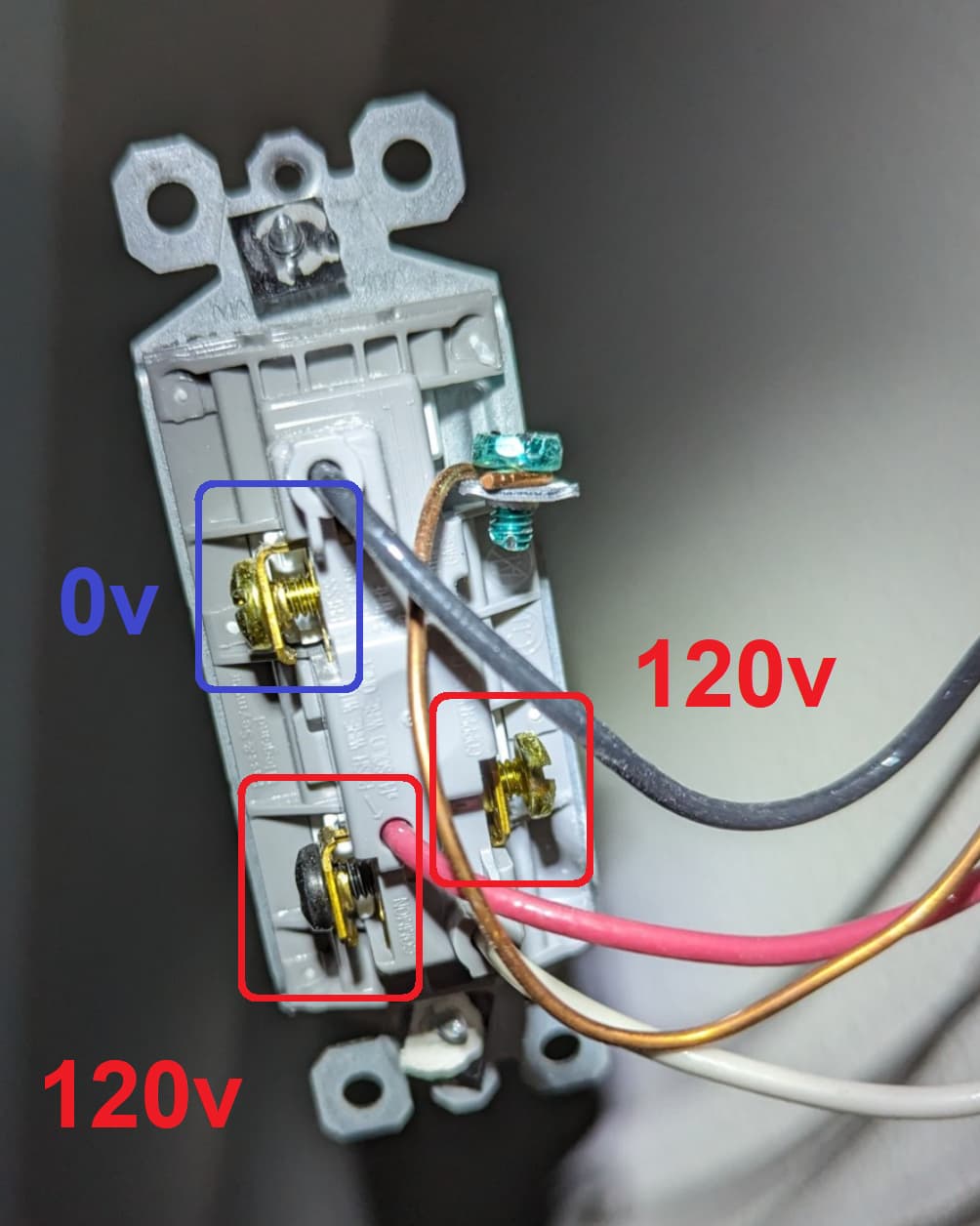
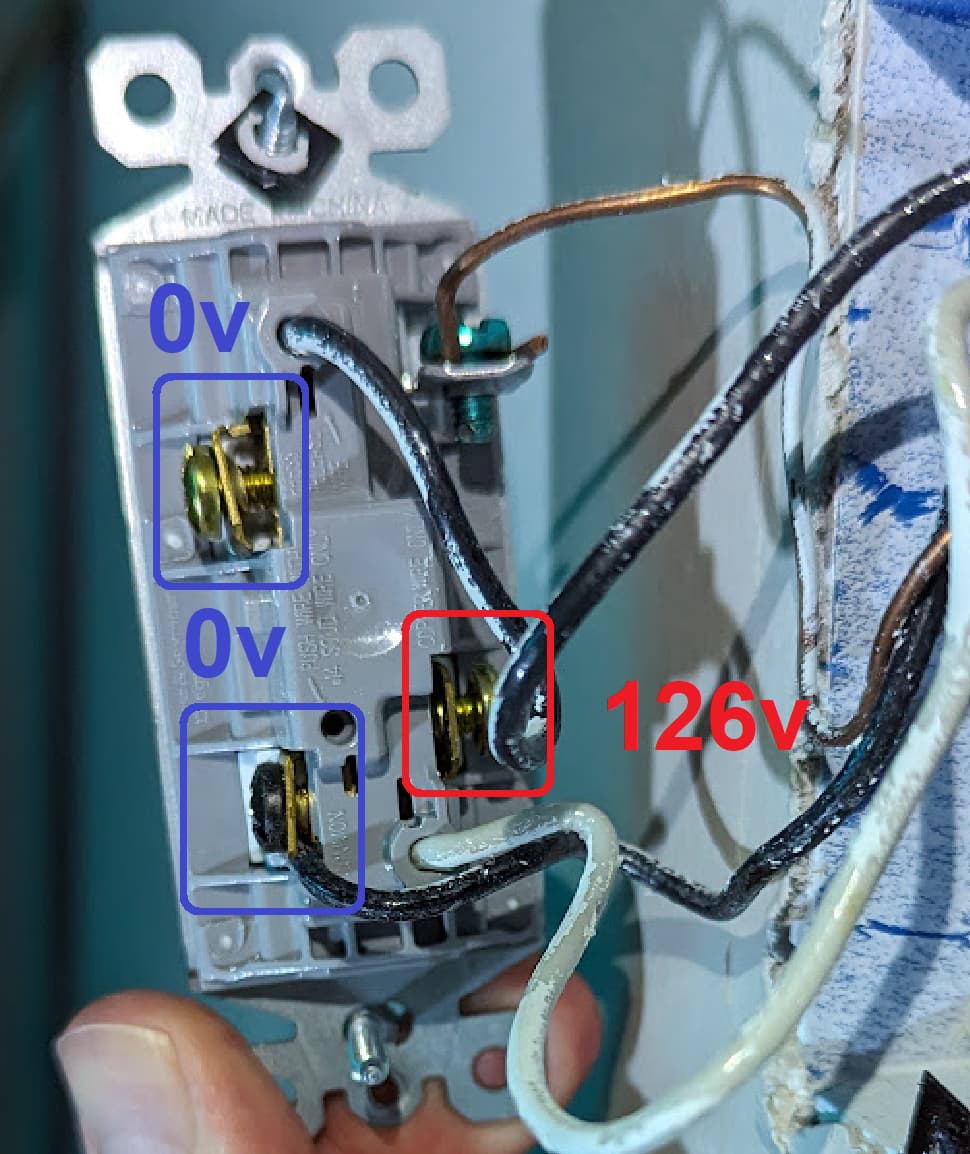
In a closed circuit situation where the load is going to the lights, all three of the 0v blue boxes in the attached images move to 120v… so that tells me that I should be following the “Load in Both Boxes (Neutral Wire Setup)” schematic; however, the power source situation seems reversed in my case where the power is going to the switch that lacks the twist-on wire nuts (i.e. putting my Inovelli switch in at this location won’t work because I only have 3 available wires at my disposal).
I definitely wish there was some standardization and better labeling in the electrical community (knowing that the line/live/hot wire is usually black but can be white/black or red/black AND the load wire is typically black but can be white while the neutral is also white but sometimes gray tells me that I can’t trust anything based on color except good ol’ reliable ground).
One suggestion I also have is that the schematic markups talk about the black screw on a switch is a universal indicator for the common wire; however, the Vocabulary section of the documentation fails to address the purpose or significance of what’s common (it appears in my case the common is where the line/live/hot wire goes in for one of my switches whereas it’s used for load in the other switch):
# Electrical Terms

- **Line:** Hot wire (120V), also known as "live" wire.
  - **Wiring Color:** Usually black, but can be white/black or red/black.

- **Load:** Wire running from switch to what it controls (e.g., bulb(s)).
  - **Wiring Color:** Typically black, but can be white.
  - **Note:** The load can include multiple bulbs or fixtures. It's what turns on and off with the switch.

- **Neutral:** Carries current back to the power source.
  - **Wiring Color:** Generally white, sometimes gray.
  - **Note:** May not be present in some houses. Often bundled together in the back of the gang box if they are.

- **Ground:** Provides a path to earth for the current if needed.
  - **Wiring Color:** Green or bare copper.

# Wiring Type Terms

- **Note:** "Load" can refer to one or multiple bulbs—anything that turns off when the switch is flipped.

- **Single-Pole:** One switch controlling one load.
- **3-Way:** Two switches controlling the same load.
- **4-Way:** Three switches controlling the same load.
- **5-Way:** Four switches controlling the same load.
- **Multi-Way:** Refers to 3-Way, 4-Way, or 5-Way setups, used interchangeably as the switch programming is the same.

# Switch Layout Terms

- **Dumb Switch:** The existing, non-smart switch.
- **Aux Switch:** Refers to the Inovelli Aux Switch or similar models from GE, Honeywell, or HomeSeer. Also known as "add-on" switch.
- **Neutral Setup:** A wiring setup with a neutral wire present.
- **Non-Neutral Setup:** A wiring setup without a neutral wire.