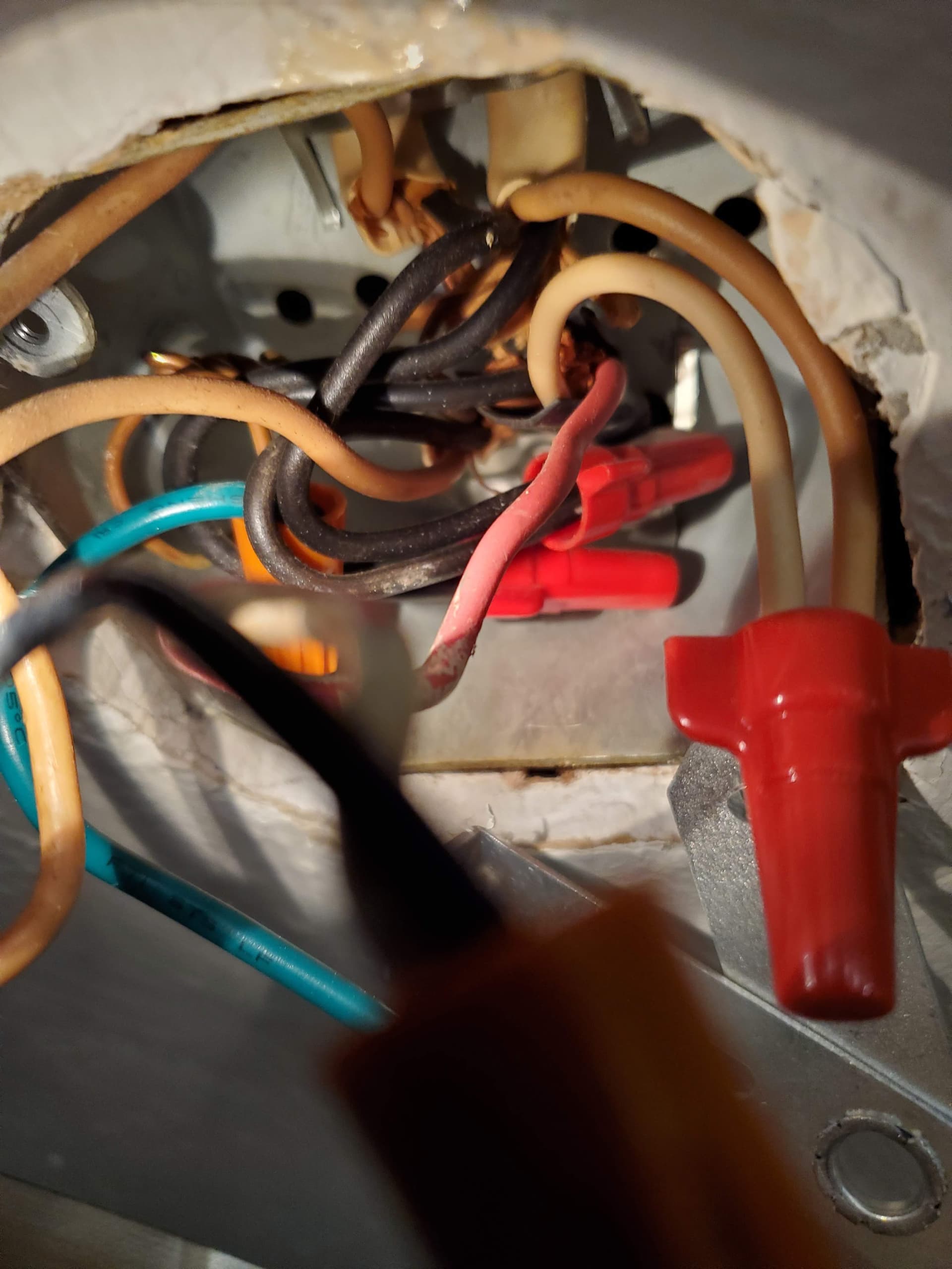
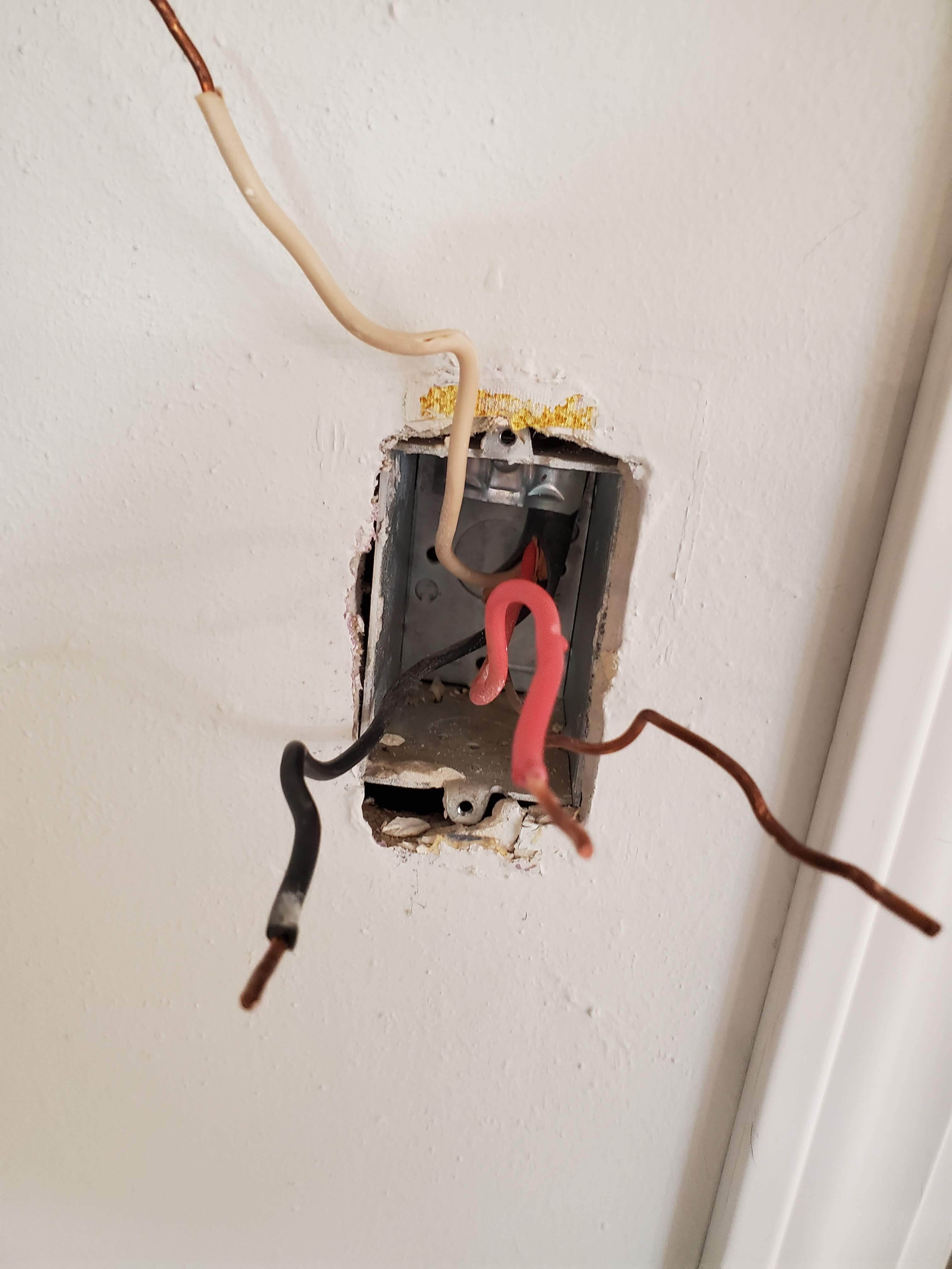
I’ve tried real hard to get all the right info here, and diagram as best I could. I can’t figure this one out. My fixture box is also a jbox for other things, it seems.
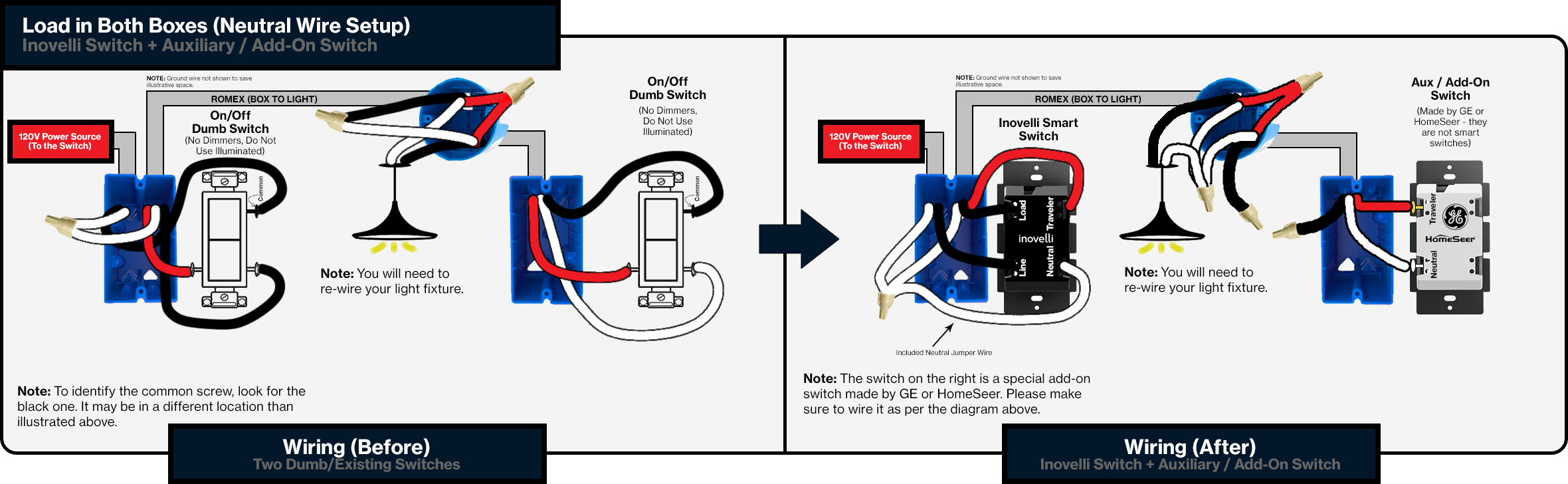
I’m looking to use an auxiliary switch on a 3 way with neutral.
Can anyone guide me on this? I’ve successfully installed several reds, one with an aux. 3 way.
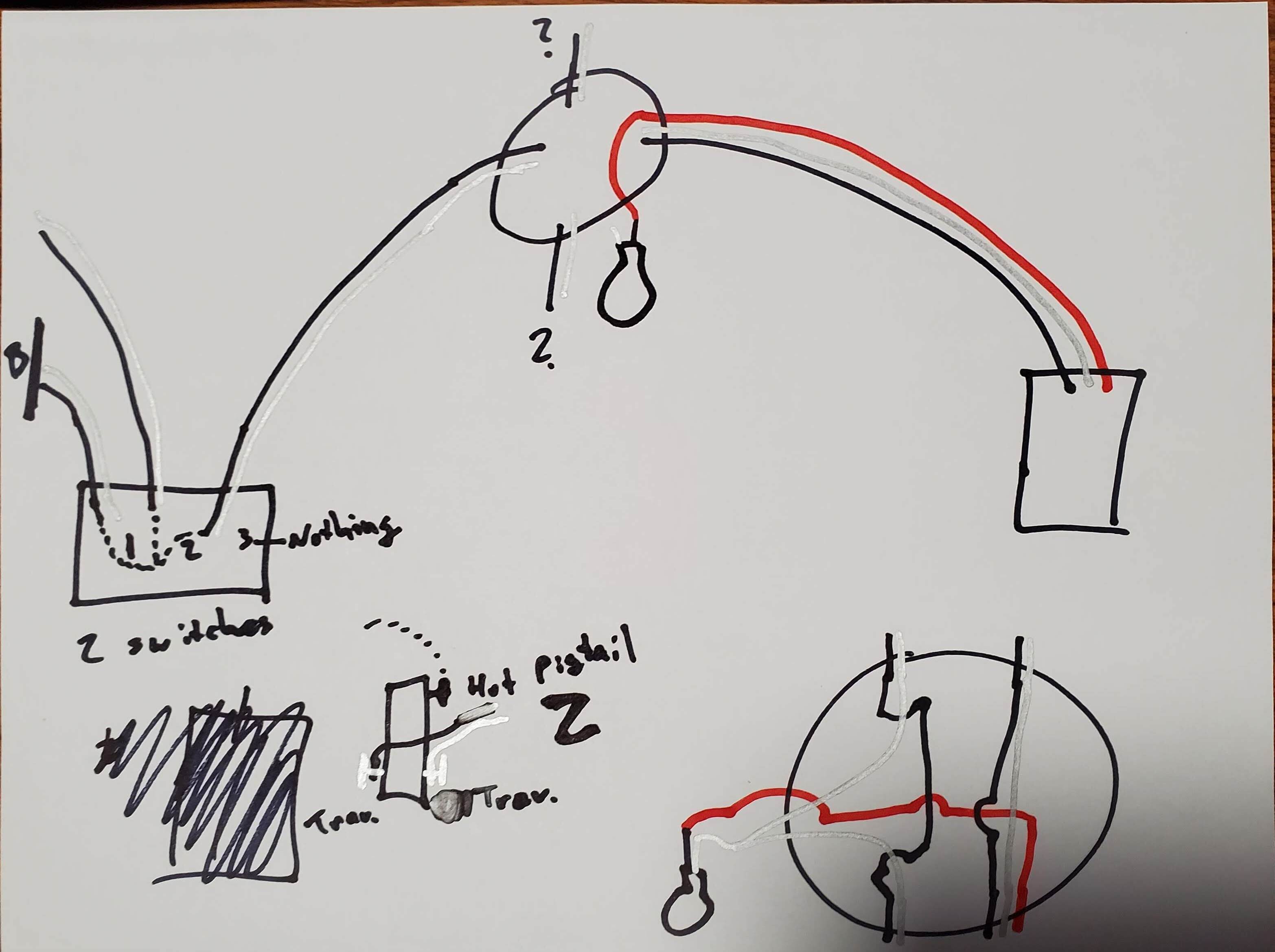
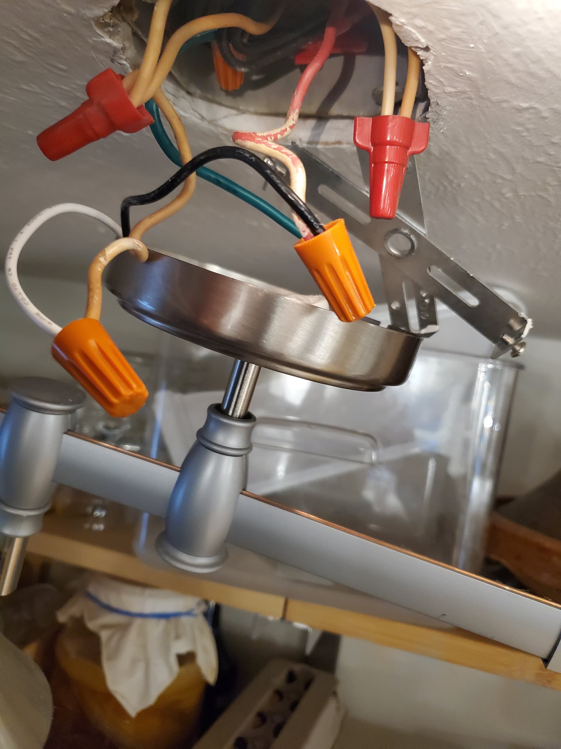
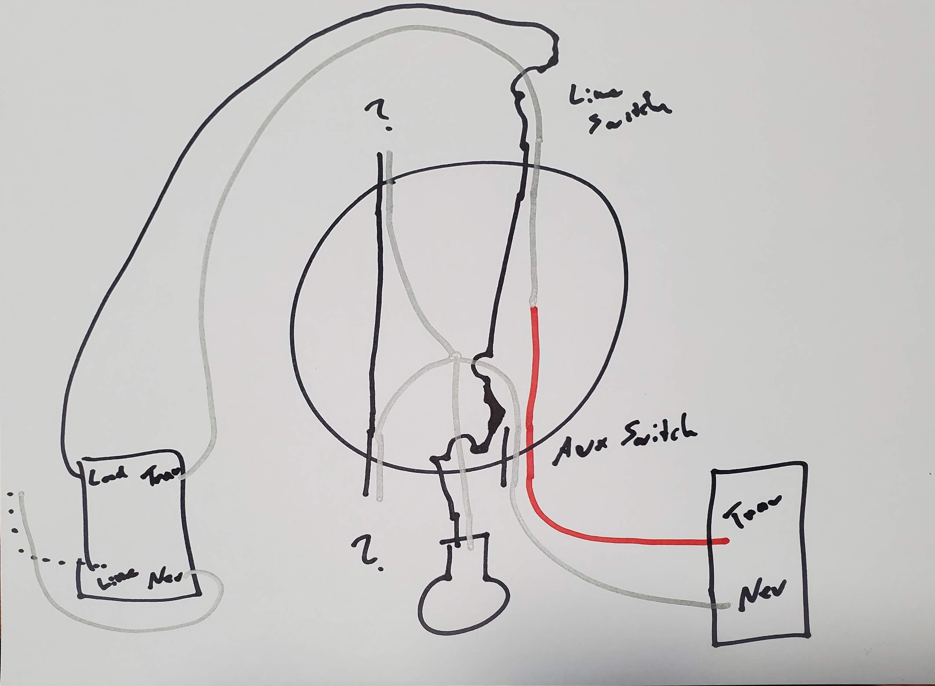
Here is my diagram, as best I can tell. I’ll clarify that my fixture box in the bottom right is simplified in that I have omitted the wire nuts, you can see that there are many in the box.
I used silver for neutral, it’s easier to see if you blow up the picture.
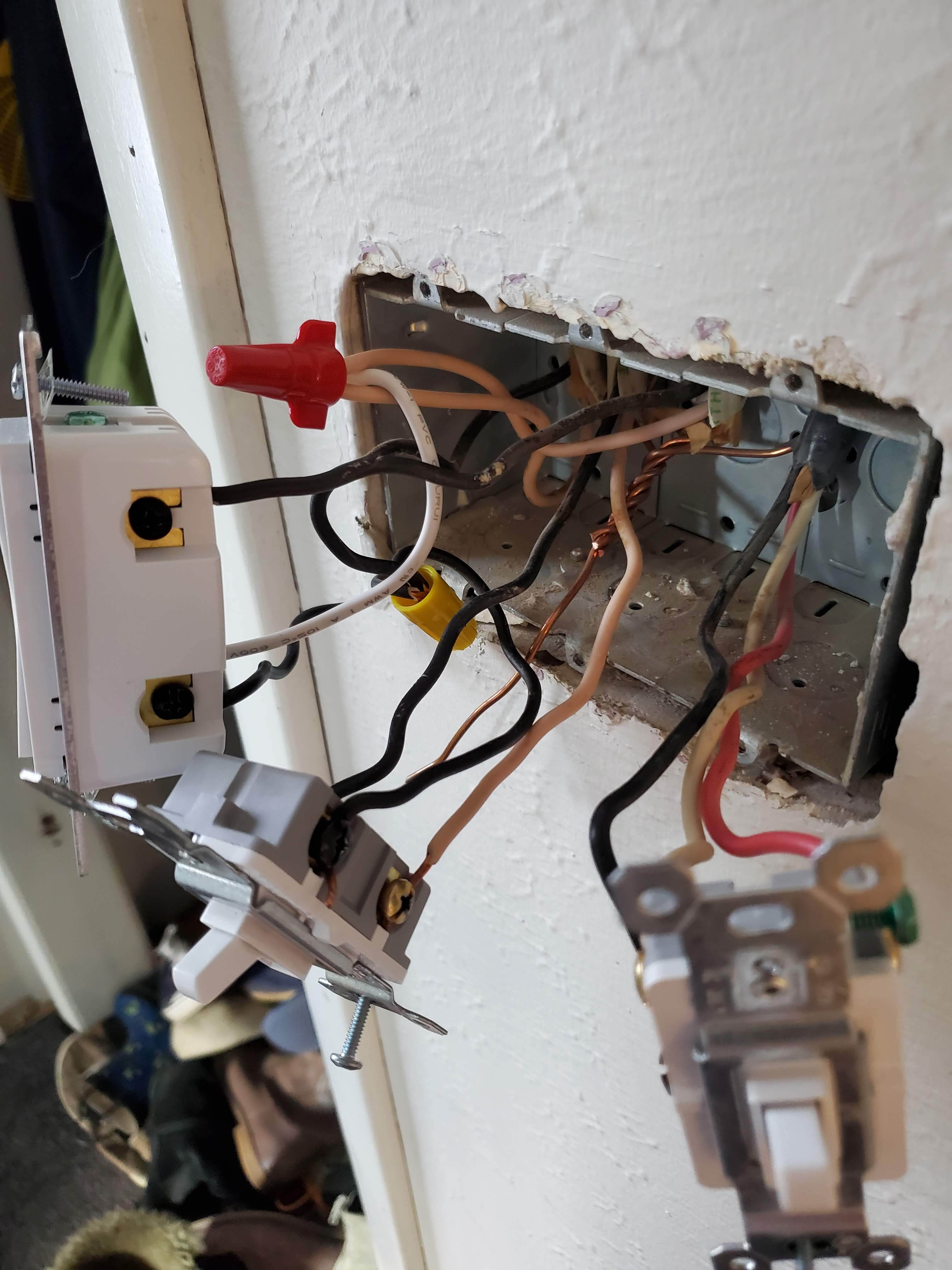
Next, the 3-gang switch on the left. The switch with the 14/3 is connected to an empty box in the basement, I think it was for previous exterior lighting.
Power in on the far left side. Simple switch on the left. Hot is all pigtailed.
So, from the looks of it this is the way I would test/wire.
Switch 2 - The BLK on the BLK screw is COMMON - this is line since its connected to the line bundle (as you state). The travelers/load in a 3 way can be interchangeable as long as it’s not connected to the COM screw. So in the current state of switch 2, you could swap the BLK and WHT connected to the silver screws and it would work normal.
The neutral question brings up a interesting point. I wonder if line goes to the fixture first then down to the first box. Is switch 1 the white wire neutral on that switch?
So in box A, switch 2, I would wire the BLK wire connected to BLK screw to line on the Inovelli (you can confirm with DVM). Install a white pigtail to the neutral bundle where the other switch 1 is connected with neutral. Connect BLK from silver screw to load, connected white on silver screw to traveler of Inovelli switch.
At the fixture, I would connect the BLK wire coming from the Inovelli Load to the light (swap it with the red). I would then wire the red wire to neutral bundle (top left with 3 white wires). Cap the BLK wire going to the AUX switch.
At Aux switch side, connect red to neutral and white to traveler. Cap BLK wire that goes to the fixture.
I tested, and there is just the one line in the 3-gang box. Neutrals are also bundled there.
3 gang box has 4 14/2 in it. One is line/neutral, one is basic switch 1, one is the ino red, and one is dead. Everything is bundled off the (I think) breaker wire.
Sounds like we are in agreement on the wiring. Does my most recent diagram look right?
Yes, diagram does look accurate. We just want to ensure you’re not stealing neutral from another circuit. I’m hoping line from load center is coming to the fixture first, then down to box A.
It’s against NEC to utilize another neutral from a different circuit. You could always ohm it out to ensure the BLK/WHT line in box A is coming from the fixture box to be 100% sure.
With a DVM, you select Ohm function. Secure power at the load center. At the fixture, tie the BLK and WHT wires that we assume are going to box A together with a wirenut. At box A, use the meter to test resistance. You can turn on the audible speaker to test also, but you’re basically looking for a resistance reading (low number). It shouldn’t read OL or XXX Mohm. More like .1 ohms or something like that.
Thanks, basically just tying off our assumed power (1 of the 2), and checking that there is almost zero, but not zero resistance? and presumably ~0V once disconnected.
Correct. Definitely should be 0VAC if correct circuit breaker is off. If not, then it will be when you wire the hot/neutral together Then you can check resistance. Wire in itself will have a resistance value, so you won’t see 0 ohms unless your meter can’t read that low. If it’s a basic meter, you may see 0. Basically we just want to ensure those wires are in fact the wires in the fixture.