I am looking for some help in getting my switch situation figured out.
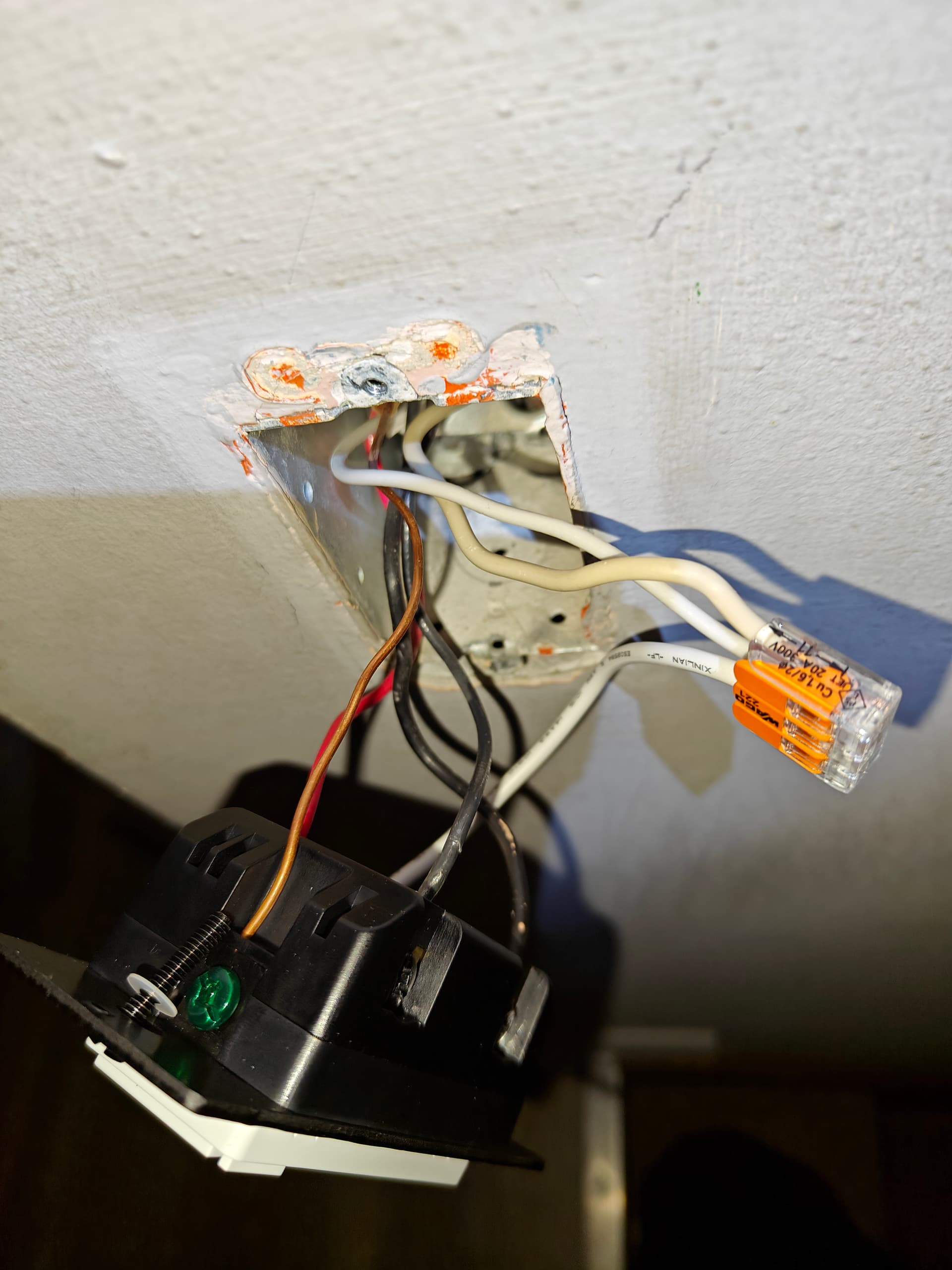
The current state is working with an inovelli Blue Series VZM31-SN and a regular dumb switch.
This configuration is working, but I ordered an inovelli AUX01 to go along with it to give me brightness control on the other end.
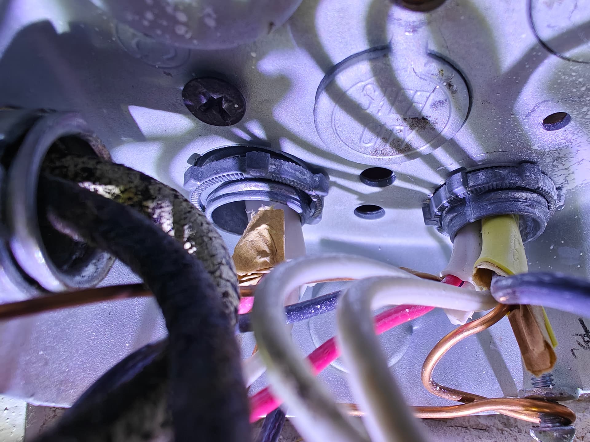
For further context in the junction box wiring, these switches are powering an array of overhead lights in a drop tile ceiling. Some wires going to the lights have tape indicating they are load (even though they are white).
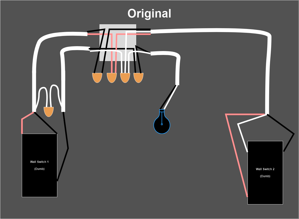
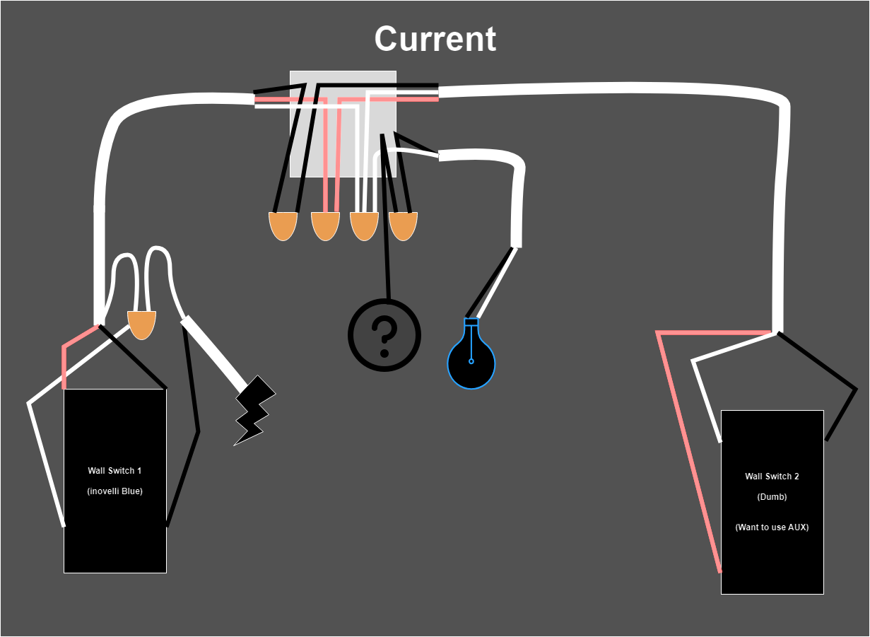
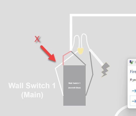
Here is my attempt at a wiring diagram:
(Original Wiring)
(Smart Wiring before AUX)
I would insert another diagram, but I am limited to 5 embedded images.
The only difference is the nuetral pigtail to Switch 1.
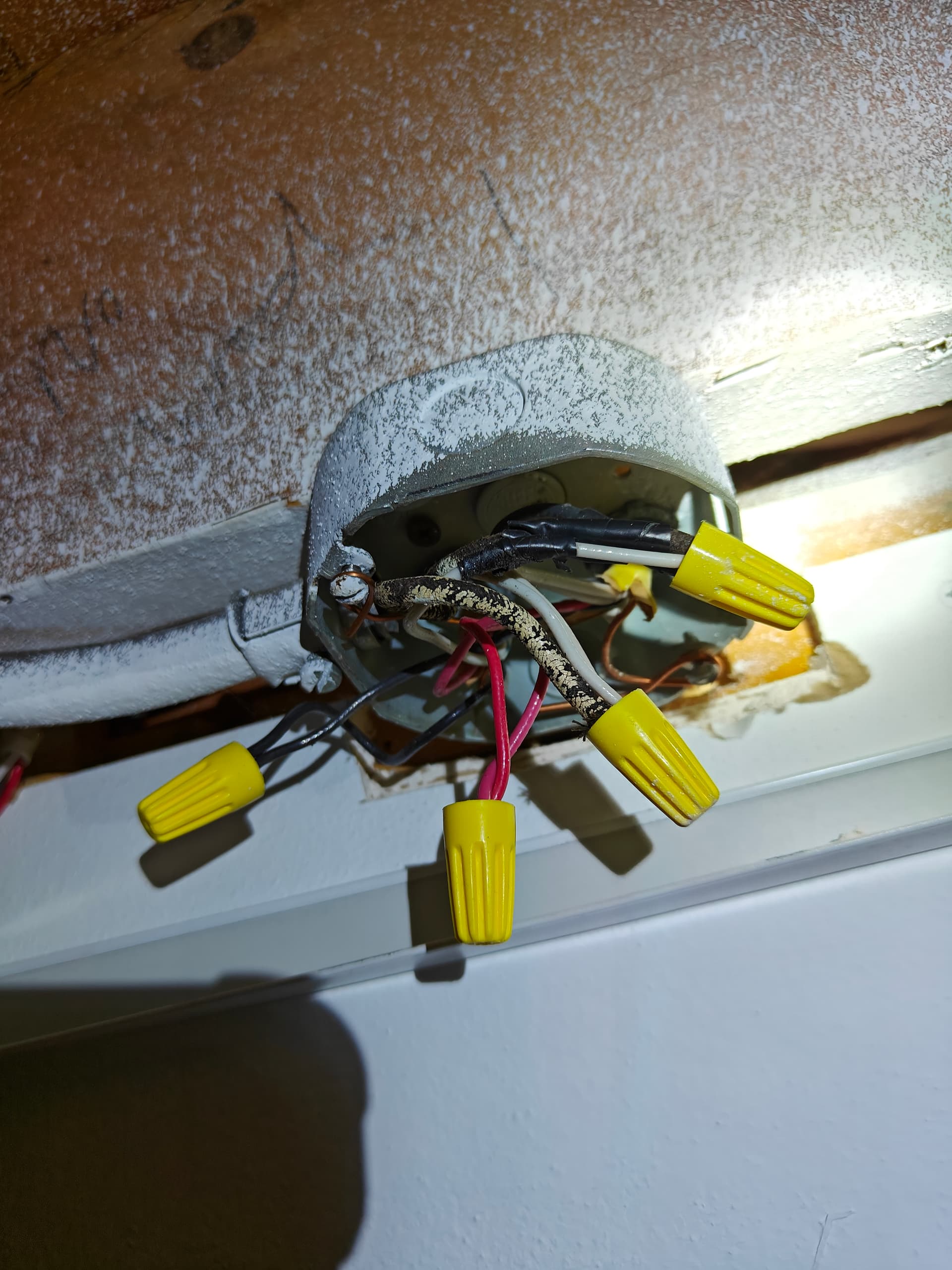
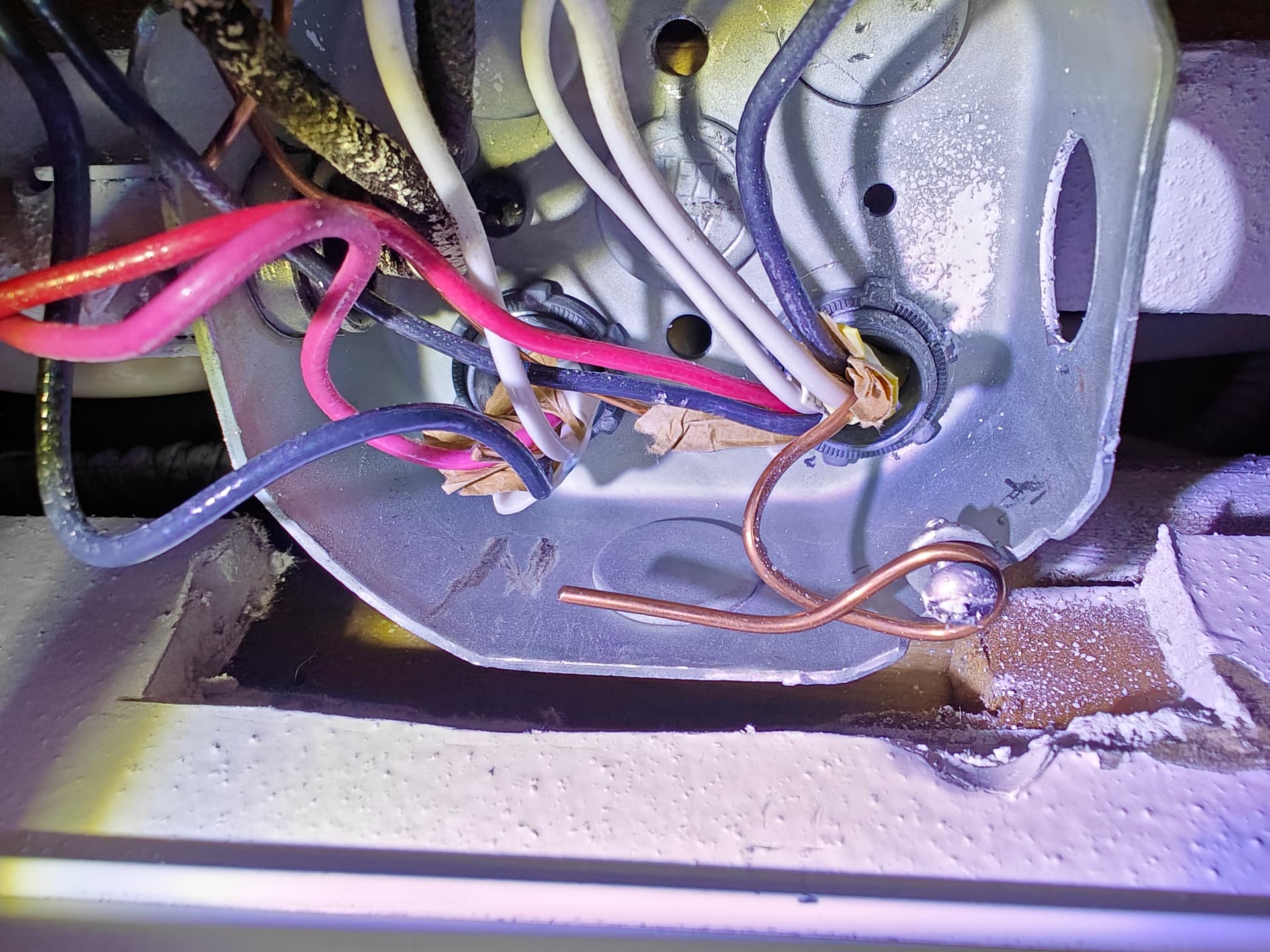
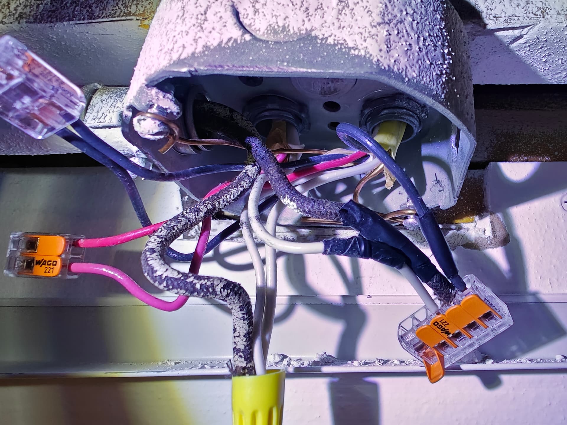
It’s all a little confusing with how many wires there are for the multitude of lights in the junction box.
But I am assuming It would be one of the sets in there. There are more wires connected to the wire nuts in the junction box than I put on the diagram. I focused more on the wires for the switches.
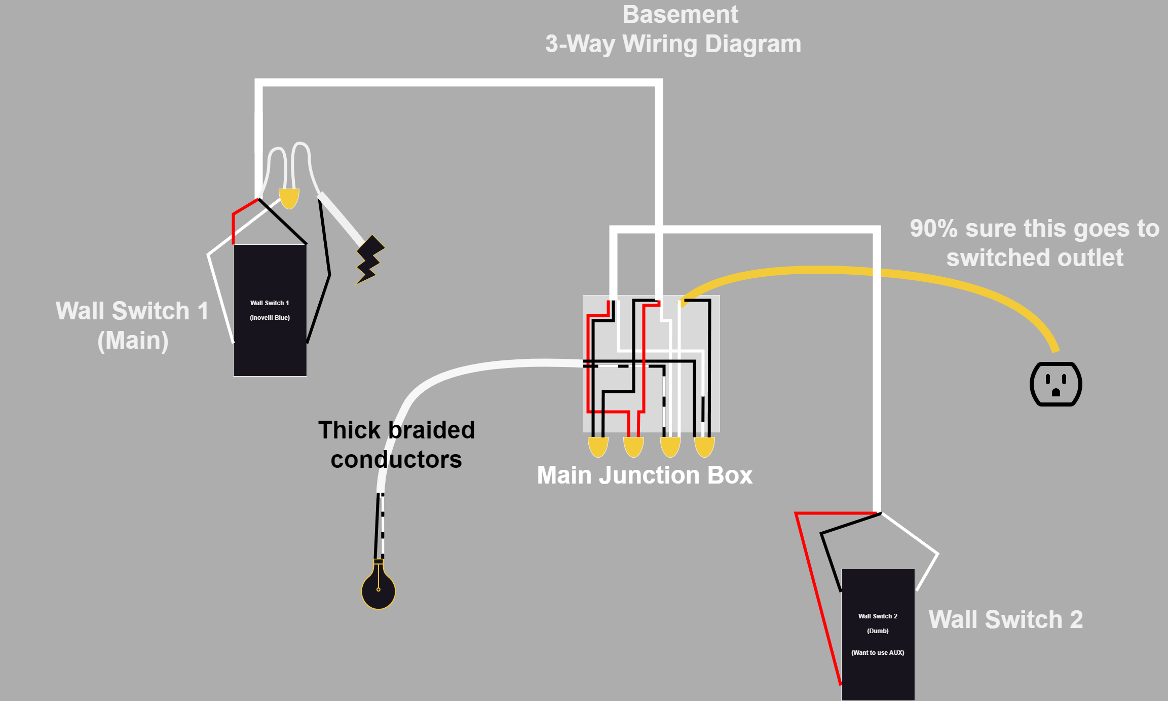
I suspect the BLK wire with the thicker insulation is the line, but you’d need to confirm with a meter.
This is a line to junciton box (or light fixture) first. I’m sure there’s some drawings already on the forum of this type of setup, but you may need to track down some voltages first.
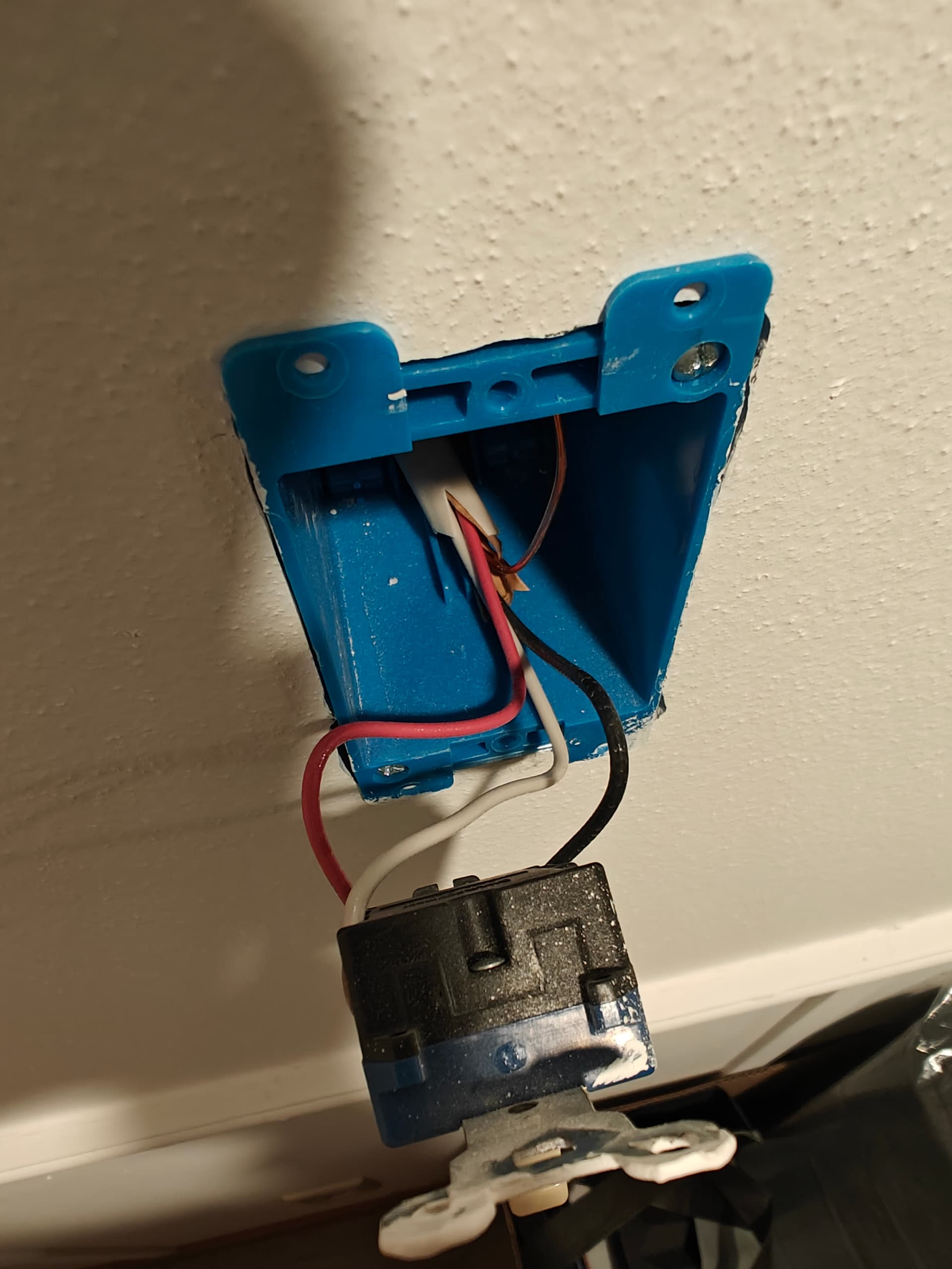
I just tested all the wires with a NCVT when the lights are turned off. The only wire/s at the junction box that had power were the red wires connected together. When I disconnected them only the red wire coming from my Switch 1 had power. Going back up to that switch there were two wires with power the red wire that was going down which I found had power previously, and the black wire paired with the nuetral wire on the right side of the diagram. I will adjust my diagram acordingly because this would mean that this romex is not going to the junction box at all and is likely where the power is being delivered from.
@harjms I think this is closer to what is acutally going on, but it just leads me to more confusion now as to how to lights are actually getting the power.
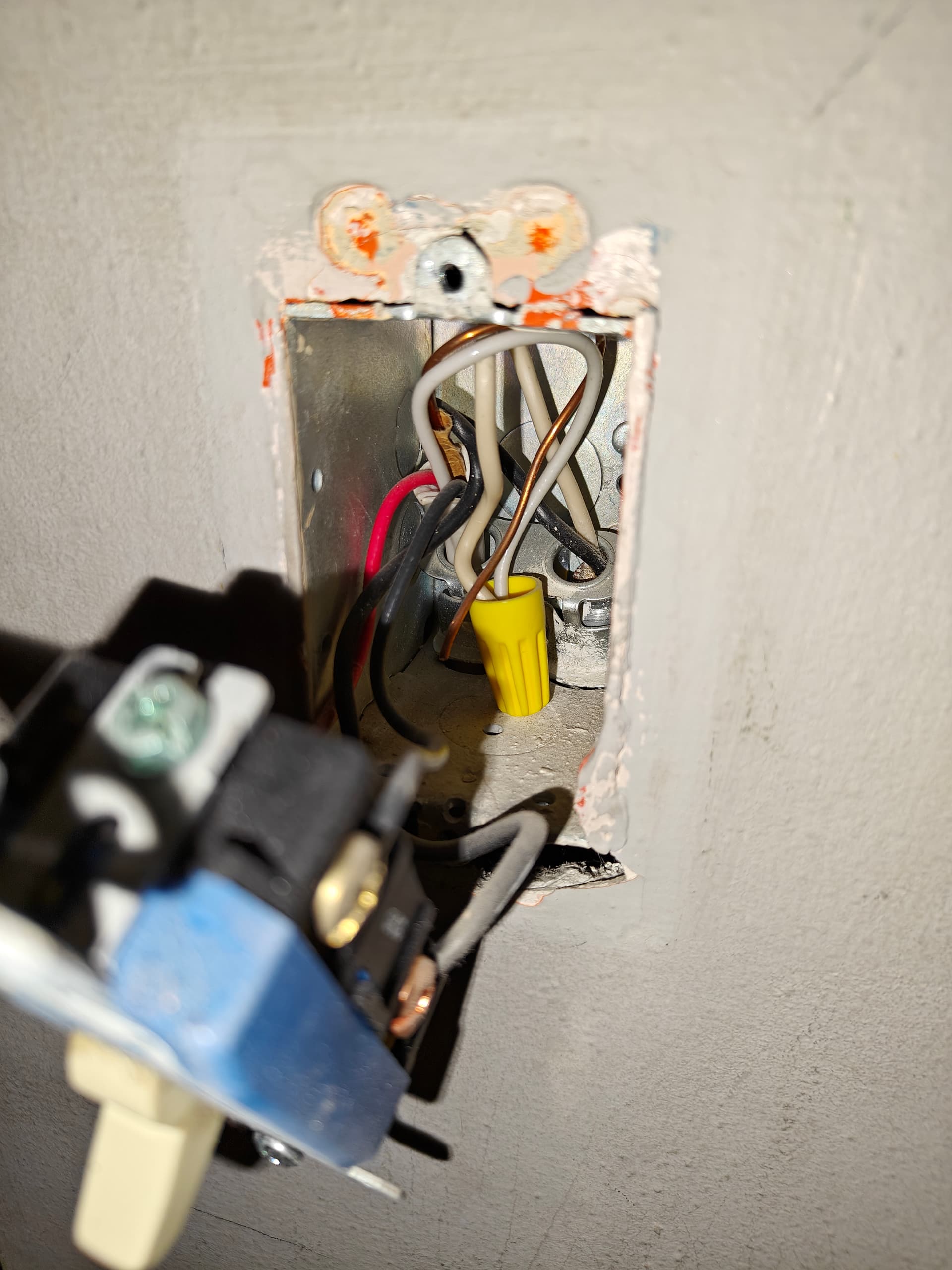
I’m seeing something different, maybe. Pull the conductors fully out of dumb switch box 1. It looks like there is a 2-wire AND a 3-wire in there. The 2-wire may be the panel. Can’t tell for sure without a better pic.
Definitely better on the drawing. However, remove the white neutral conductor connection to the switch. Only the black and red conductors from the 3-wire connect to the two traveler (non-common) screws on the switch. If you look at the neutral bundle with the yellow cap, you’ll see only two conductors.
@Bry I am a little confused as to why I should remove the nuetral pigtail for the smart swich there, to my understanding that would not allow the smart switch to be powered, no?
(After reading that again I think you got mixed up with my original dumb switch at Switch 1 instead of the inovelli blue)
In the current wiring situation the inovelli blue seems to be working perfectly fine, but I am trying to get the inovelli AUX to work instead of the current dumb switch at Switch 2.
The AUX only has a nuetral and a traveler so I’m assuming something needs to be changed with the 2nd black wire connected between the switches maybe? Not exactly sure.
I tried looking at the example wiring diagrams, but I didn’t seem to have something quite similar last I checked. I might give them another look in the meantime.
Yep, exactly. I though your drawing was documenting the existing dumb switch configuration. That neutral is required and correct for the Inovelli. Sorry 'bout that, Chief!
Aux switch needs a traveler and a neutral. Based upon your drawing, the red conductor gets passed unchanged through the junction box, so connect the red to the traveler terminal on both ends.
That leaves the neutral. At the Aux, connect the white to the neutral terminal. Cap off the black conductor.
In the junction box, take the white conductor from the 3-wire going to the Aux and connect it to the neutral bundle. Cap off the black from the 3-wire to the Aux.
At the Inovelli, connect the black from the 3-wire to the load terminal. At the junction box, connect the black from the Inovelli’s 3-wire to the black 2-wire going to the light(s).