Hi All - I was successful getting some wiring feedback on another set up so I thought I would post a question about another set up.
I have a gang box with four switches, two single pole, four way switch and three way switch. This is the wiring currently in place.
Coming into the top of the gang box there is the following:
two wire romex - black wire leads to a bundle of nutted black wires and the white to the neutral bundle
three wire romex - black and red goto brass terminals on four way switch and white to neutral bundle
two wire romex - black to black terminal on three way switch and white to neutral bundle
Going out of the bottom of the gang box is the following:
three wire romex - red and white to the brass terminals of the three way switch / black to the bundle of black wires nutted together
two wire romex - black to one of the single pole switch and white to neutral bundle
two wire romex - black to the other single pole switch and white to neutral bundle
two wire romex - black and white to the respective bundles
Then there are jumpers from the black bundle to the various switches filling in the remaining wiring.
I think I am pretty comfortable wiring the single poles to a smart switch just taking the line/load currently in place and jumping a neutral wire to the neutral terminal.
Just having trouble on interpreting the wiring diagram included with the red series dimmer with what is in place. Hopefully my description is helpful and I include pics below to hopefully help with the visual. Maybe @Bry or @harjms have some ideas.
For the 4-way leg, that box is in the middle of the leg so your Inovelli won’t go there. You only listed half of the wires connected to the 4-way switch, but I’m guessing that the 4-way switch has conductors from two 3-wires connected to it.
You are going to have to examine the 3-way switches belonging to this leg to determine where to place the Inovelli. Since the white(s) from the 3-wires connected to the 4-way are bundled to neutral, that suggests to me that you have a line and load in different boxes. So the line starts in one 3-way box, passes through the 4-way switch(es) and ends with a 3-way feeding the load to the light.
Take a look at the 3-way switches on the ends. One of them will have a constant hot w/neutral with the black hot (usually) connected to the common (black) screw. The Inovelli goes there.
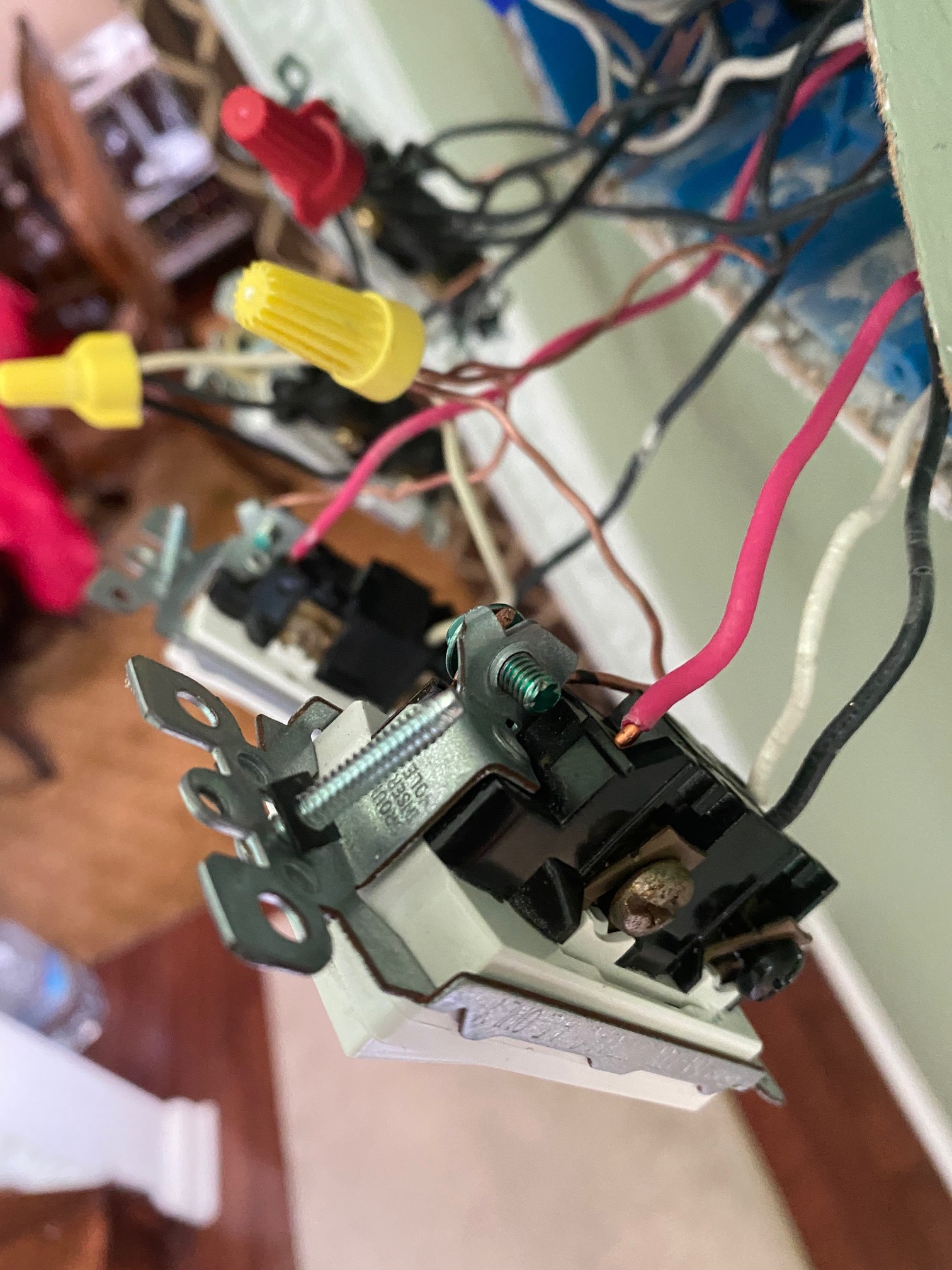
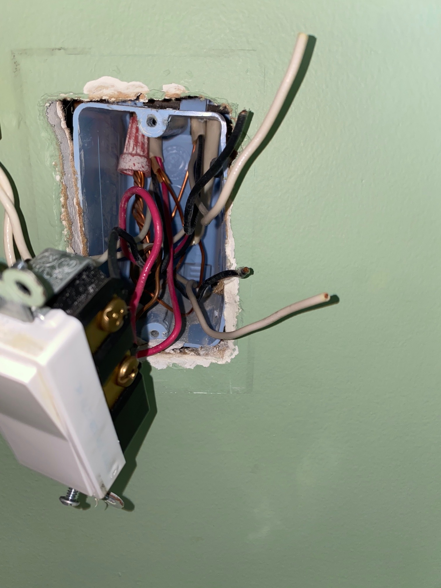
The switch that is part of the 4 way has the black and a red from a three wire romex connected to the brass terminals. There is a “white” jumper connected to the bundle of black wires that is connected to the black screw terminal in that switch.
The black wire that is connected to the three way switch right now is “common” and has no power. Do I just move that black to the bundle and pull one of the black wires that are currently in the bundle and connect to the line terminal of the Inovelli dimmer? The other switch on the 3 way does not have a neutral in the box.
First of all, take plenty of pictures and maybe mark the cables so that you can always put things back.
At this point I’m a bit confused about your 4-way switch leg. Earlier you described a “four way switch” and based on that I responded. a 4-way switch is a switch with four terminals on it that is in the middle of a 4-way switch leg. Is that what you were describing? Based on your last post, I’m now wondering if you were describing a 3-way switch that is part of a 4-way leg.
For terminology, a 3-way switch has three terminals plus a ground terminal. A 4-way switch has four terminals plus a ground screw.
So we’re still working on the 4-way leg, which means there are three of more switches that control the light(s). Is the switch you were describing a 3-way or a 4-way? (I’m referring to the type of switch, not the a description of the number of switches on the leg.)
Yes, based on your clarification, its a 3 way switch thats part of a 4 way leg (there are two other switches in a different location that control the same light). I also have a 3 way switch that has one other dumb switch that controls another light and then two single poles that control two other light fixtures. Apologies for any confusion.
Ok, so it sounds as if for this 3-way switch on the 4-way leg, there is a jumper to a bundle of blacks that is connected to the black common screw. This is probably the hot feed, but USING A METER, temporarily remove the conductor from the switch and test between it and a white neutral bundle to see if you get 120V. Put the conductor back when you are done.
Then go find the other 3-way switch as describe the Romexs and connections to it.
Yes, as you suggested above, that jumper to the bundle of blacks that is connected to the black common screw is hot (120V when tested between it and a neutral).
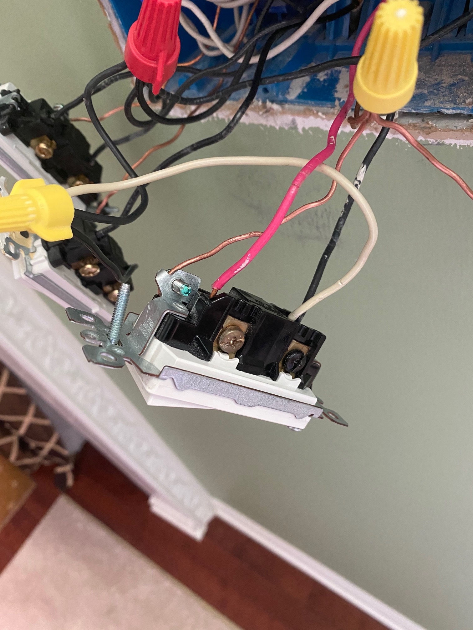
The other 3-way switch (in this 4-way leg) has a three wire romex with the red and black wire connected to the brass terminals - white to neutral. It also has a two wire romex black wire to black terminal white to neutral.
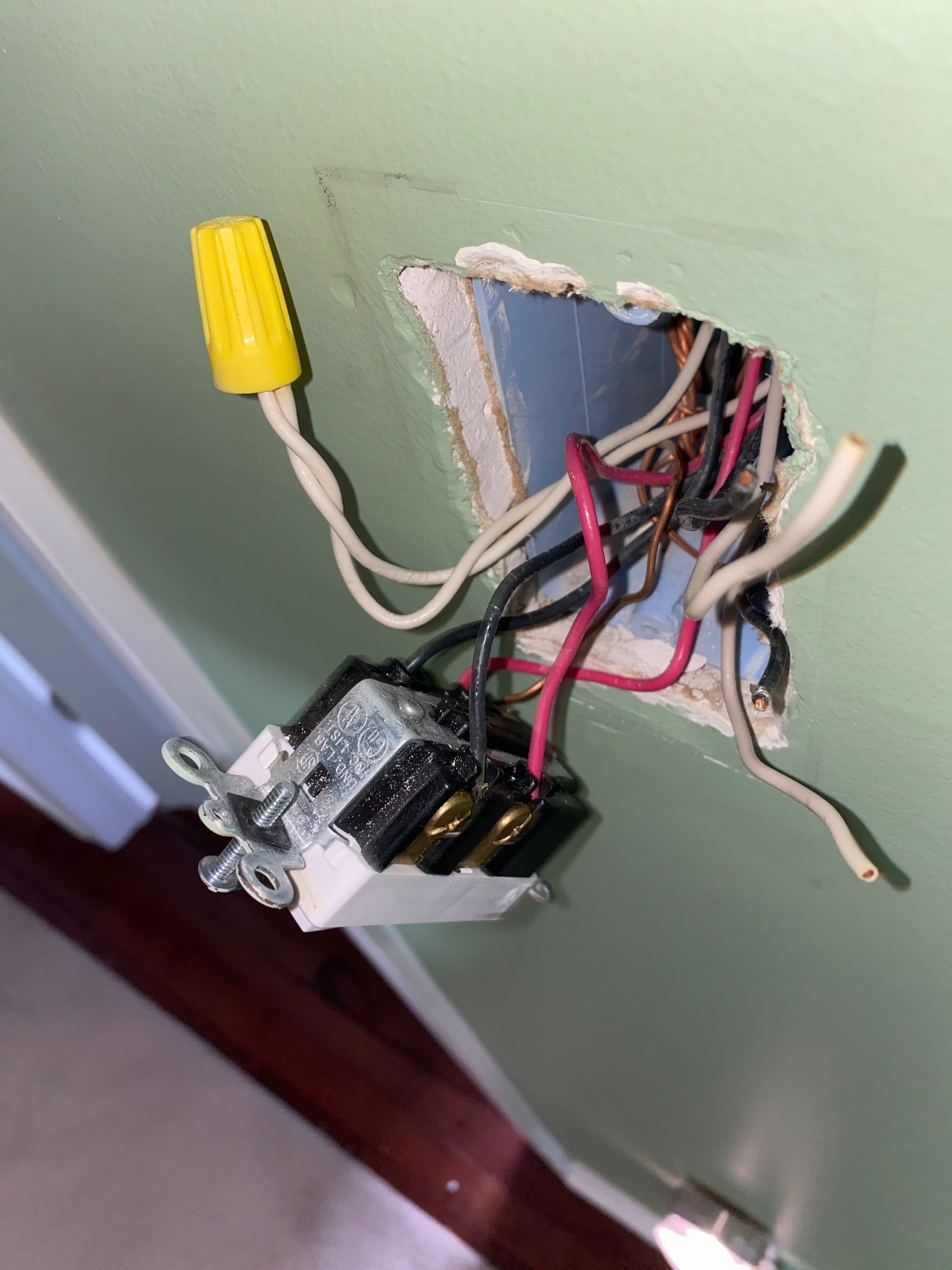
the 4-way switch (in this 4-way leg) has a two wire romex coming into the bottom and another two wire romex from the top that are not connected to anything. As you can see in the picture below the wire nut came off. I am assuming I should nut the black wires together and connect the two loose white wires to the neutral bundle.
So based on this, I am assuming the inovelli is connected in the box that has the hot wire and I should be able to use the two dumb switches as described above with no rewiring, correct?
My only confusion is how to connect the inovelli (the switch currently has a black and red from a three wire romex connected to the brass terminals and then a jumper to a bundle of blacks connected to the black common screw).
So yes to the Inovelli in the box with the hot jumper, I THINK.
Your 4-way switch description does not sound correct to me, maybe. (And no picture that you referenced.) You have a 3-wire leaving the first switch which would then go to the 4-way switch. At the 4-way switch, I would expect two 3-wire Romex, one from the first switch and one to the last switch.
But your description says you have a 2-wire and some loose stuff I don’t understand because I can’t see it. The best thing to do would be to post pictures of the 4-way pulled out so I can see the connections and into the box.
Is the 4-way working properly, even with the disconnected wires?
There is a way to do a 3-way with 2-wires, but it’s not typical.
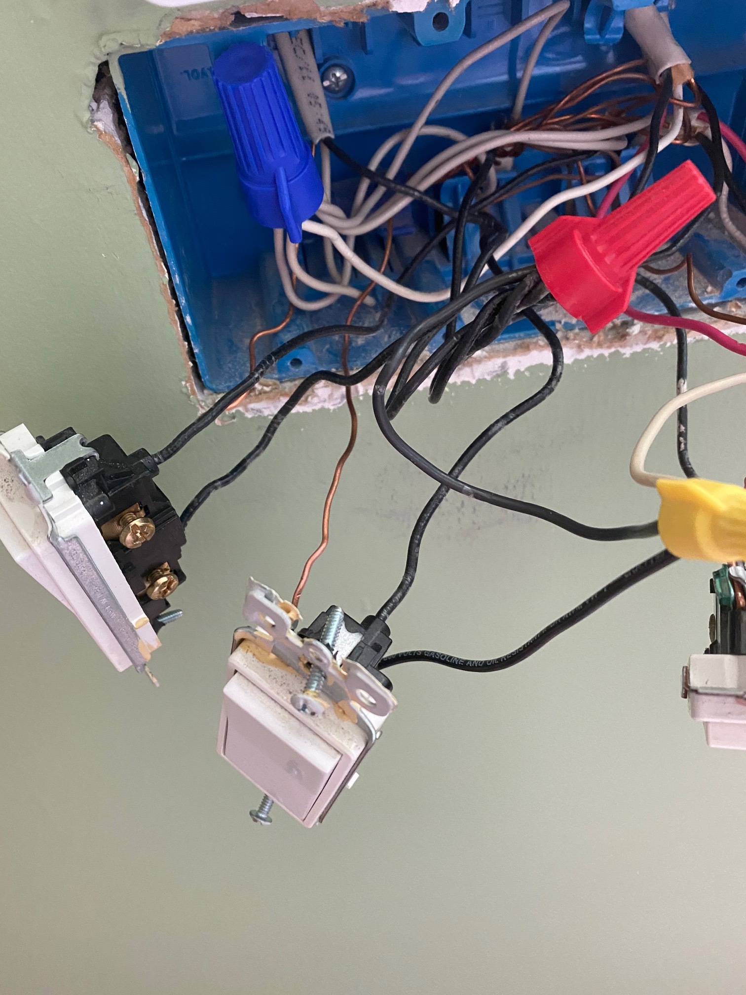
here are the pics of the 4 way switch - I did get the 4 way set up to work by itself by installing the inovelli in the box with the hot jumper. Inovelli and two dumb switches worked as expected.
Then I went and tried to wire the 3 way leg that controls my chandelier and everything stopped working. Lights were flickering, buzzing and the other inovelli (on the 4 way leg) wouldnt work anymore it blinked and crapped out.
Glad you got the 4-way working so I don’t really need to see the pics of the switch. But what is up with all of those unterminated/uncapped conductors??? Are any of those live? Even if they are not they should not be uncapped. Plus you may have an overloaded box with all of those conductors. The box capacity calculation doesn’t matter if the conductors are in service or not.
I would assume they were capped and got loose when I pulled out the outlet to take a pic. I just capped the blacks together and the whites to the neutral and seemed to work. But stopped working when I tried to work on the other switch.
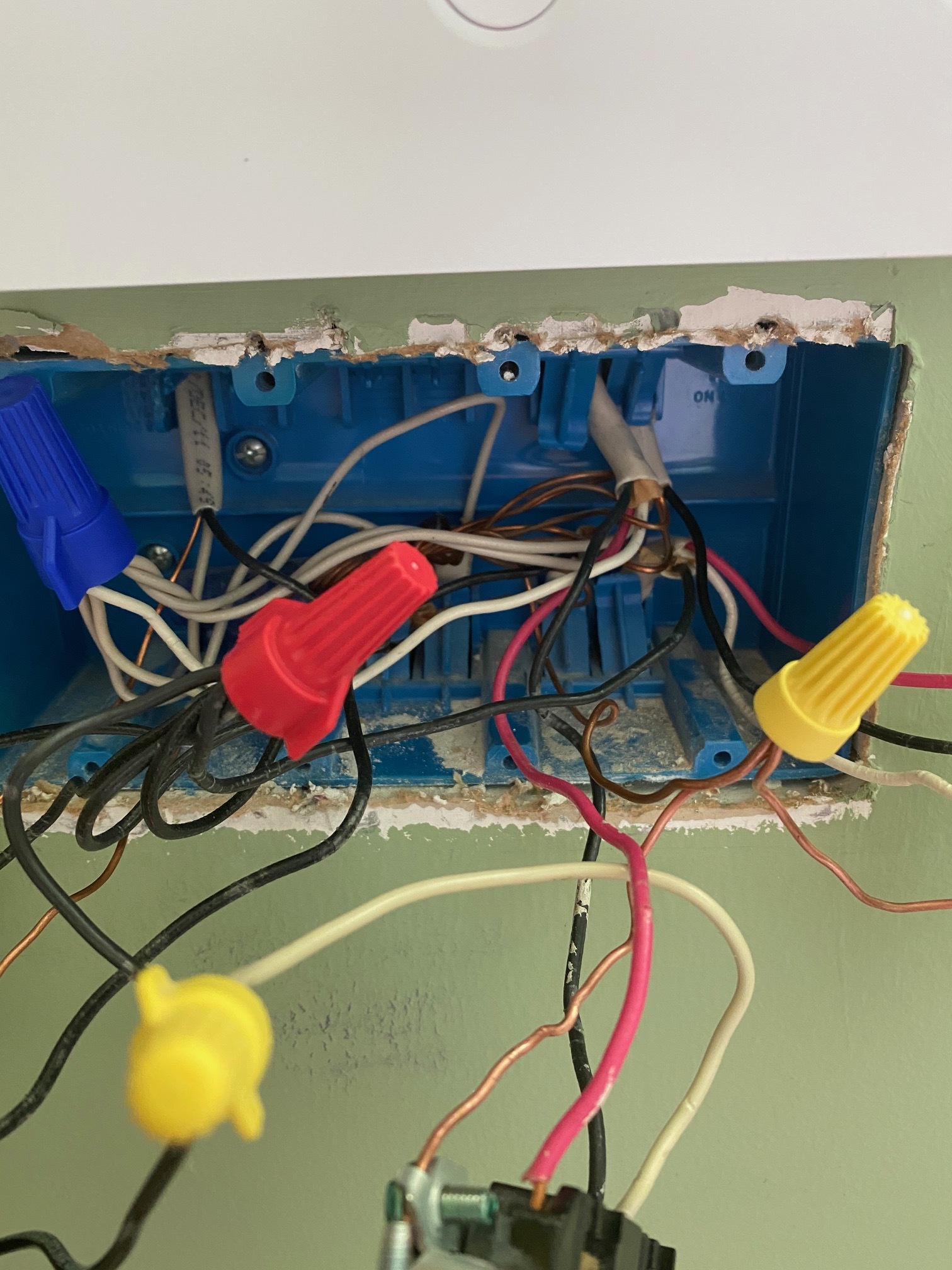
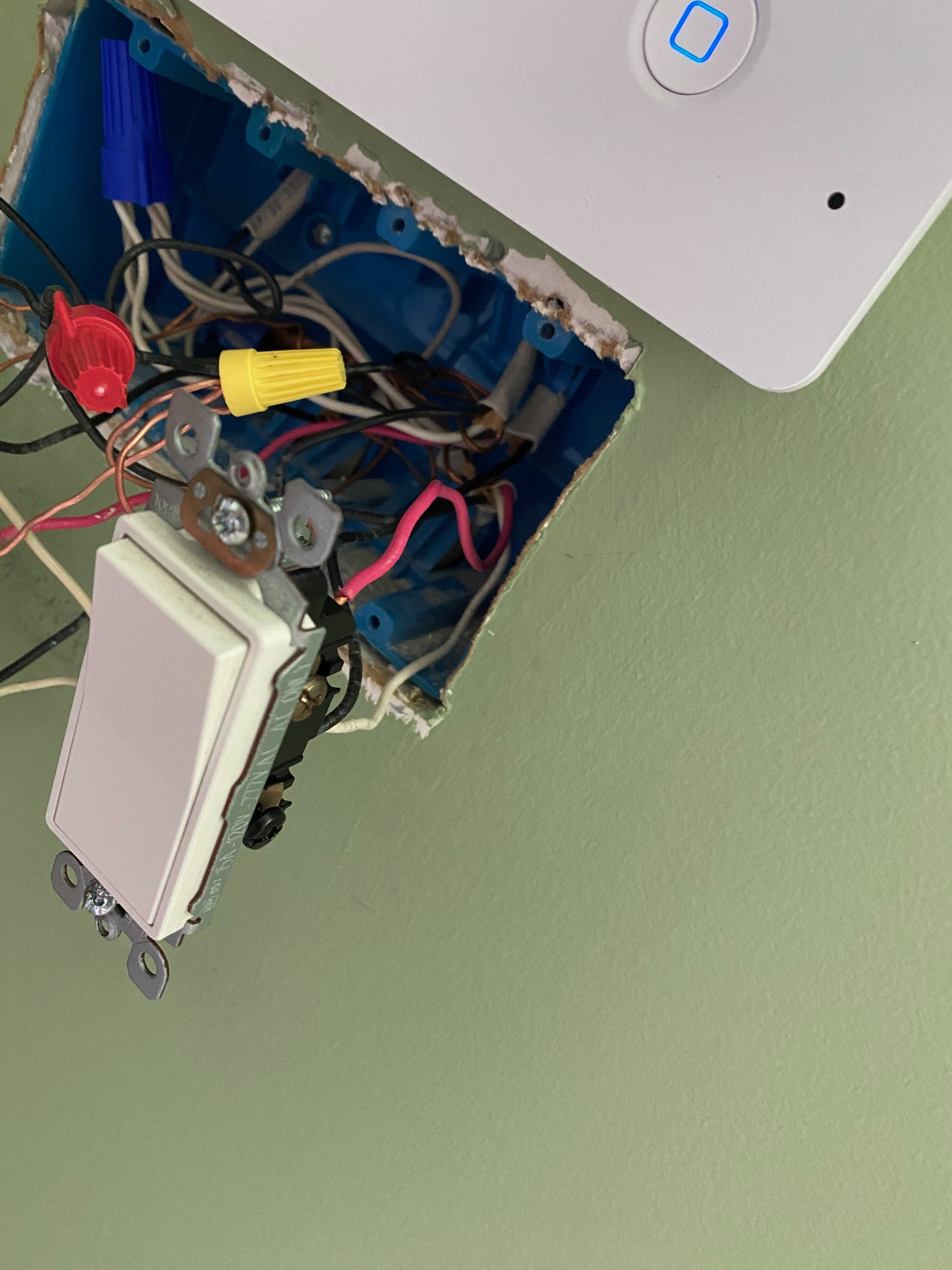
Here is the wiring in the box currently and I am trying to wire the 3 way switch in the pic. I removed the black wire currently connected to the common terminal and tied into the bundle of black wires with the red cap. It seemed as though there were two possible “black” wires that were nutted that would replace the black currently in the switch. But nothing seemed to work and killed the 4way leg.
Edit: there are only two sets of 2 wire romex that get attached to the bundles. The one you see on the top left and there is one that comes from the bottom of the box. I would assume that you would connect the black from the 2 wire romex on the top left to the line terminal on the inovelli. But i am not sure what the other 2 wire romex from the bottom of the gang box that is just connected to the bundles is for.
Put the 3-way back together the way it was so it’s working and then double-check to make sure the 4-way is working. It’s a lot easier to understand when you’re looking at something that’s working.
Glad you got it back. You need to start by looking at both sides, so pull both 3-way switches and take a look at the wiring. Need to know how many Romex and what type, 2-wire or 3-wire are at least partially connected to the switches and where the remaining conductors are connected.
The other side of the 3 way leg just has a three wire romex - no neutral.
Could the issue be that I have that bundle of black wires and the common from the current switch is getting connected to that bundle when installing the inovelli?
I don’t understand your question, but put it aside for the moment. There is a logical method to doing this. It involves understanding your circuit. Let’s take it one step at a time.
So on one end of your 3-way, only a single 3-wire is connected. Which conductor is connected to the black screw on that switch?
Are the two loads terminated in the same switch box? It’s no different than wiring one load. Just put both loads on the load terminal of whatever you wind up using. Make sure that you do not exceed switch capacity.