Brand new here and need some assistance for wiring. I’m excepting a white series dimmer switch along with the aux switch tomorrow. I’m running into a setback when looking at the diagrams vs the current setup of how to install. These do not seem to match the current setup.
Currently there are two switches (one switch at the top of the stairs, and the other at the bottom of the stairs). These both control the same light fixtures. Both lights are located at the top of stairs.
However I believe the switch at the bottom is a dead end and is not a true 3 way. Being a new member I was unable to upload pics, so I’ve attached links.
Wiring Setup - Note: Yellow underline is hot. All wires were tested with a non contact voltage tester.
Top Left Box = All wires taken apart and tested
Top Right Box = Current wiring setup.
Bottom Left Box = Different configuration of testing
Top Switch Current Wiring
Bottom Switch Wiring.
The idea was to use these switches with smart bulbs / smart bulb mode, that way I’ll be able to control each light independently vs both at the same time.
Any advice or support would be greatly appreciated.
Thanks for your quick response. I’ll do my best to clear up any confusion. In the drawing image. The page was divided into four quadrants, each quadrant contained a scenario. Any wire that became hot at either switch during the test was underlined with yellow.
First Quadrant, Top Left Quadrant of Drawing Image - All Wires Disconnected,
Yes, the top box has a 2 wire (white and black) on left side , and a 3 wire( white black and red ) on right side ; inside the box.
Yes, the bottom box has a single 3 wire (black red and white) inside the box.
No, the only hot conductor is the white from the 2wire in the top box. All other wires from top and bottom boxes were not hot.
Second Quadrant, Top Right Quadrant of Drawing Image - Current Wiring Setup.
This is how the switches are currently wired.
Top Box: The white(hot conductor) from the 2-wire is connected to the red wire from the 3-wire in the top box. Doing this made the black from the 3-wire also hot .
Bottom Box: This also made the black and red wire hot from the single 3-wire
Bottom Left Quadrant of Drawing Image - Test
Top Box: When the white (hot conductor) from the 2-wire is connected to the black wire from the 3-wire This made the black and red hot from the 3-wire
Bottom Box: This also made the black, white and red wires from the single 3-wire hot
One ceiling light box for sure, the other ceiling light is in the middle of the stairs, it’s still possible , just a process.
Okay thanks. So now this is looking like a non-neutral config in the top box. That makes a bit more sense since the white from the 2-wire is connected to the red from the 3-wire.
If you disconnect the two conductors (black and white) from the 2-wire and touch or wire them together, do the lights turn on?
Ok, great. So that is going to be a non-neutral config with the top box as the primary box.
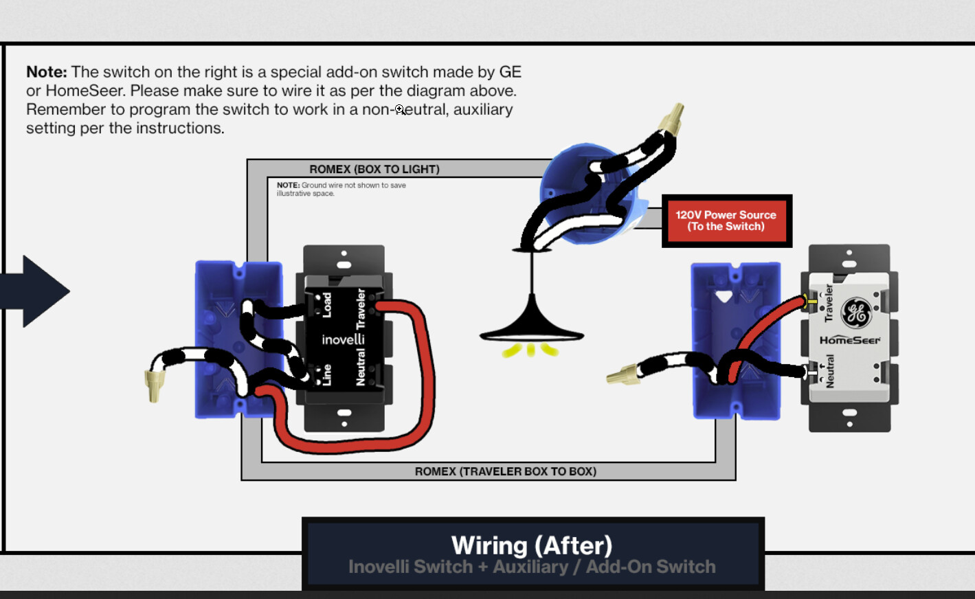
The first stage is to put the Inovelli in the top box and wire it as a 2-way non-neutral. The white hot from the 2-wire goes to the Line and the black from the 2-wire goes to the Load. Leave the 3-wire completely disconnected for now and make sure the Inovelli is working as a 2-way.
The switch should auto-detect as a non-neutral and I believe the default setting is 2-way, so you should be good out of the box. You may need to change it from on/off to dimmer, however. The quick tap sequences are in the manual below.
Once it’s working OK as a 2-way, add the Aux. You’ll use 2 of the 3 conductors on the 3-wire. In the top box, red to Traveler and black to the 2nd Line hole. In the bottom (Aux) box, red to Traveler and black to Neutral. Cap off the white from the 3-way in both boxes.
You’ll need to use a quick tap sequence to reset to 3-way Aux.
The switch should arrive shortly, and I will report back as soon as it does.
Will I still be able put the switch for smart bulb mode? Ideally I would like to put smart bulbs in each light, and program the buttons via HomeKit for independent control on each “bulb / light” once in this mode.
Yes, but you may need to install a bypass at the light. The non-neutral works when enough power is passed to it. With smart bulbs that don’t draw much power, the bypass will help. Smart bulbs with non-neutrals can be a bit finicky, but try it and see how it goes.
As I mentioned before, get it going as a 2-way first.
I installed it all per your detailed directions, thank you again. Went great minus some flickering due to led bulbs in both lights as excepted.
However, as soon as I went to change it to smart bulb mode, this is where it went a little haywire. The switch and bulbs started basically power cycling / flickering repetitively ; to the point I cut the power immediately, as the switch became inoperable too.
Is this something that the bypass would correct? Or is there something further that needs to be addressed?
Note : Light 1 in middle of the stairs is a chandelier and has 5 bulbs, the other light in the corridor has only one bulb.
I’m not sure with multiple boxes. I think most people would install them in the first box but it seems to me that it is electrically the same if you put it in the other.
In theory you only need one, but there have been instances where individuals have needed more than one to get the desired effect.
Thanks again for all your help - the setup is working great now with no issues related to power or flickering.
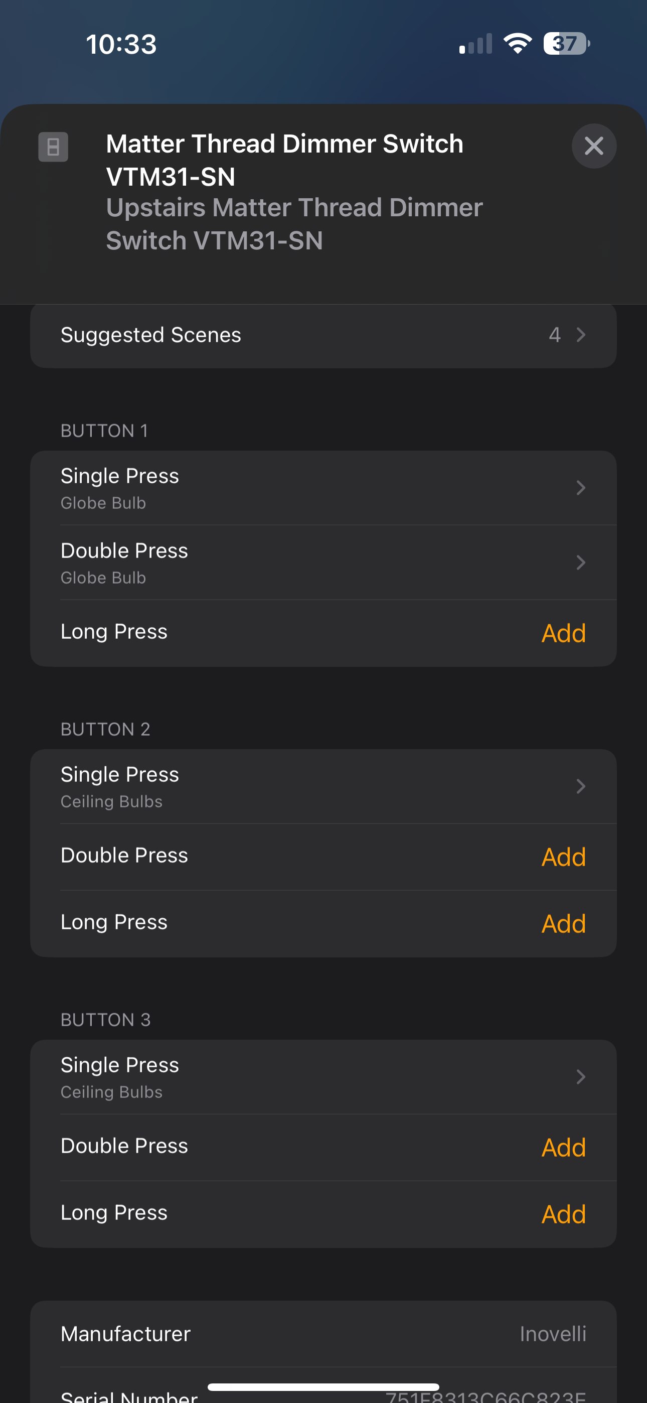
I’m only running into one issue. I’ve configured button mappings on the main (top) switch in HomeKit, and they function exactly as expected. However, the AUX switch isn’t mirroring those actions properly — the button behavior is inconsistent.
For example:
• On the main switch, a single press of Button 3 turns on Light A, and a single press of Button 2 turns it off.
• On the AUX switch, a single press of Button 1 unexpectedly turns off Light A, even though it’s configured to control Light B.
I’ve tried rebooting my Home Hub and ISP router, and I’ve also performed a factory reset on the switch twice, but the issue still persists.
Any thoughts on what could be causing the mismatch in button actions?
Unfortunately, I don’t have any experience with the White series.
As I understand it, the button presses on the Aux are not mirroring the button presses on the Dimmer.
On the Blue series, P123 configures if Aux buttons presses will mirror the Dimmer or if the Aux buttons have their own unique scenes. I just looked through the White documentation and I don’t see that as an option.
So maybe you have to independently set the scenes for the Aux itself? I don’t know Homekit, so this is just a WAG on my part. Hopefully a Homekit user can comment here.