Has anyone see a 3 way wiring like below? For the life of me I can figure out what I am doing wrong. Not sure if related but it seems like the 2nd switch in the 3 way has all three are live.
[Switch 1]
12/2 Light Black → Common Terminal on Switch 1
12/3 Red → Traveler Terminal on Switch 1
12/3 White-> Traveler Terminal on Switch 1
[Switch 2]
12/3 Red → Traveler Terminal on Switch 2
12/3 White → Traveler Terminal on Switch 2
12/3 Black → Common Terminal on Switch 2
1st switch box
12/3 black to line
12/2 white to natural bundle
Are you testing with a multimeter or non contact voltage tester? It sounds like a standard 3-way? Based on your description box 1 black is line and box 2 black is load. What are you trying to install? Smart switch and aux or 2 smart switches?
Yes, from your description, it’s a line and load in Box 1.
If I’m understanding your description correctly, the line is supplied in Box 1 and is connected to the black of the 3-wire, where it is sent to Box 2 and connected to the common terminal. It is returned switched via the red and white conductors on the 3-wire. Those travelers are connected to the traveler terminals of the Box 1 switch.
In Box 1, the 2-wire load is connected black to the common terminal of the switch, where it receives the switched hot sent back from Box 2.
The neutral paired with the hot source remains in Box 1. The white of the 2-wire going to the light is bundled with it, providing a neutral to the light.
You are correct that there is no neutral in Box 2, but that is correct as there is no need for it there. All three of the conductors in that box (i.e. the 3-wire) are used for hot routing.
The drawing you posted is correct according to the description you provided.
Need to see everything, including the connections to the working dumb switches.
Which side are you wiring the switch to?
If the dumb switch powers up and then kills power to the smart switch, then that suggests the line is in the other box. That’s not what you described, however.
Ok, that’s not going to be the Line box, so disregard what I said about boxes switched.
Let’s fill in a couple holes:
[Switch 1]
12/2 Light Black → Common Terminal on Switch 1
12/2 - White → ???
12/3 Red → Traveler Terminal on Switch 1
12/3 White → Traveler Terminal on Switch 1
12/3 Black → ???
I believe from your description and from how it should be that the 12/2 white is bundled with a white bundle and the 12/3 black is bundled with a black bundle, but I need you to confirm.
12/2 Light Black → Common Terminal on Switch 1
12/2 - White → neutral bundle where the other 2in1 is pigged tailed too
12/3 Red → Traveler Terminal on Switch 1
12/3 White → Traveler Terminal on Switch 1
12/3 Black → line bundle where the other 2in1 switch line is pigged tail to
Perfect, thanks. So the wiring diagram that you posted is correct for your configuration. I am not sure if you followed that before, but you’ll notice that when it’s wired according to the diagram, there is no way the dump switch can cut power to the Inovelli because that switch is wired directly to the hot.
No changes in Box 2.
You will have to remove the black from the 3-wire from the hot and connect it to the black from the 2-wire. Then pigtail the hot bundle to the line terminal of the Inovelli.
After wiring, you will need to set the switch type to three-way toggle.
My responses are based to the information you posted. You should use a meter to test for the line. But if it is as you described, I cannot imagine what the issue would be.
You posted that the dumb switch would turn the Inovelli on and off. If you wire it according to the diagram, that is impossible because the Inovelli is wired directly to the hot.
However, if you want to test that, use a meter to test between the hot and the neutral bundles and then go flip the dumb switch back and forth to see what happens. I would be very surprised if the dumb switch effects the hot feed in the other box, at least as you have described it.
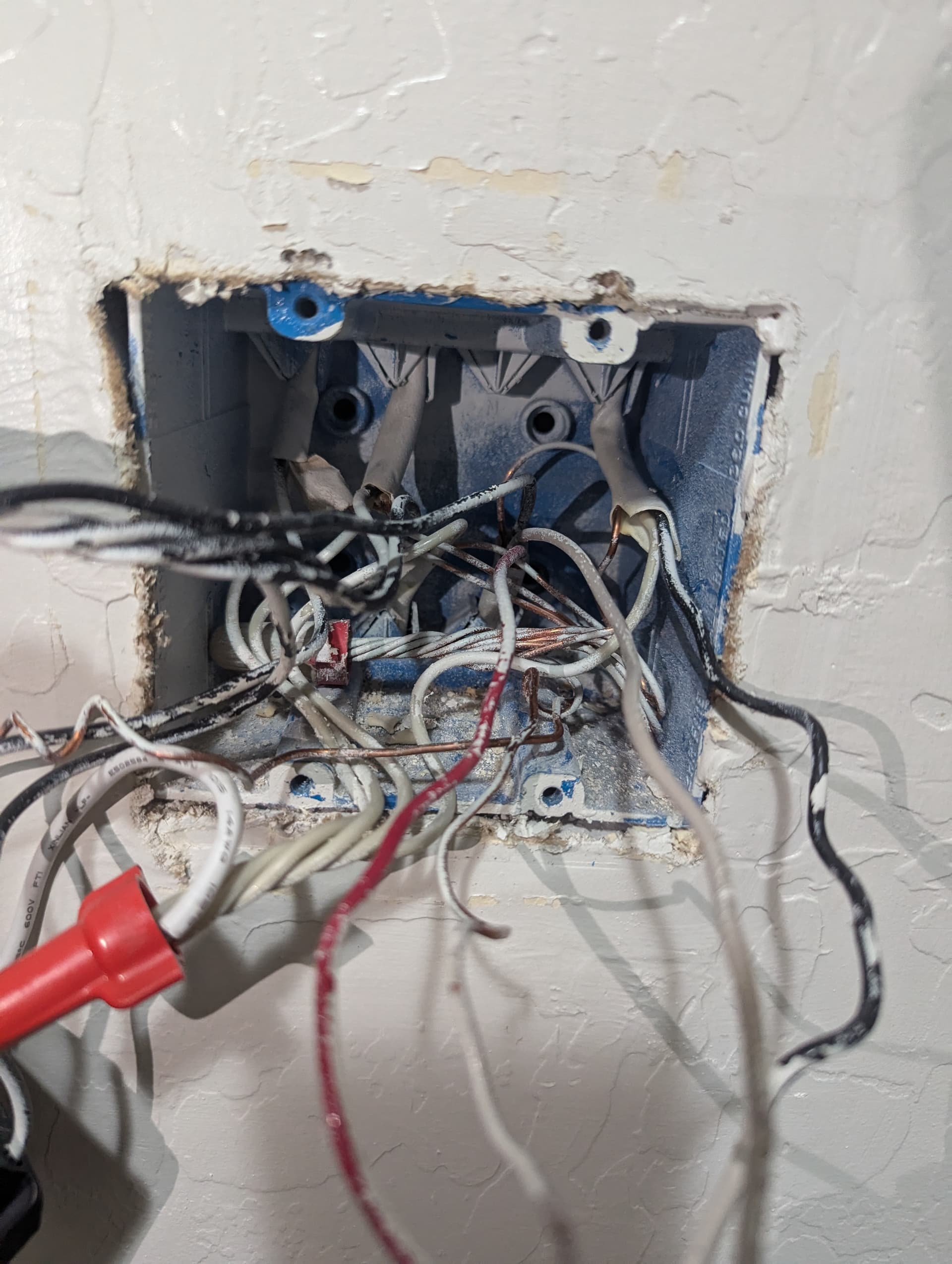
Are the two switches in that box on different circuit breakers? I am asking because I see what I believe are to distinct neutral bundles.
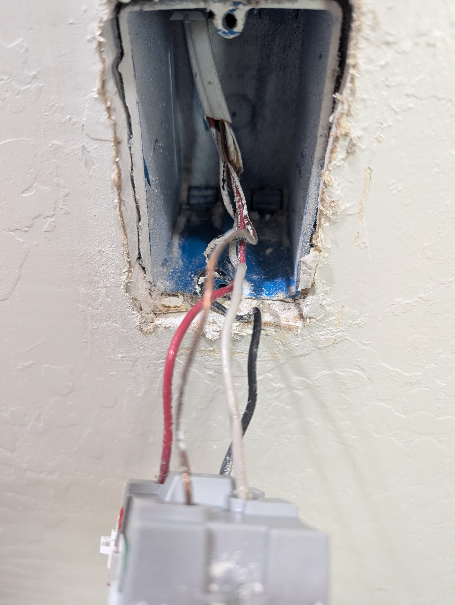
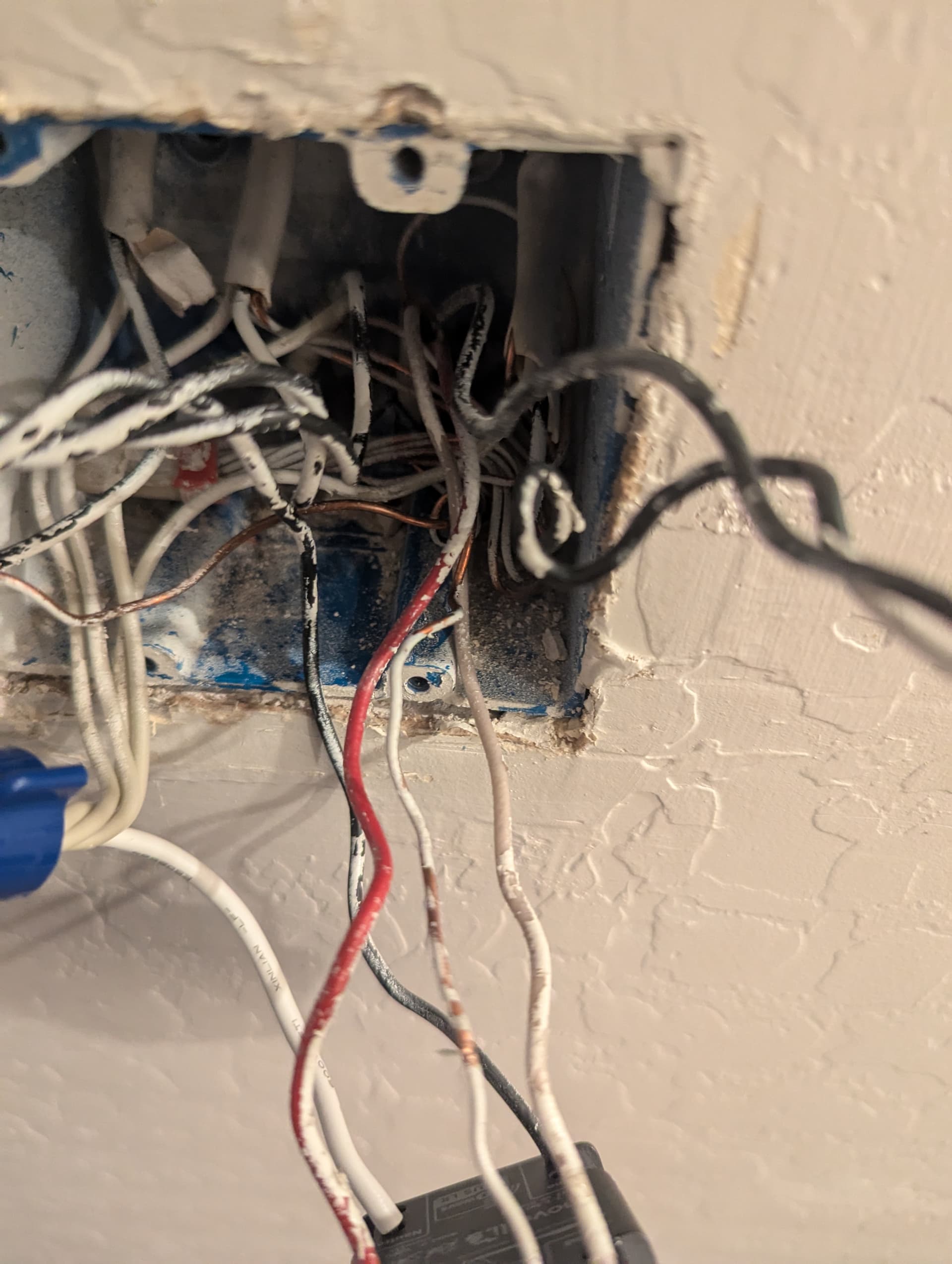
It’s still a little tough to see into your box. You need to get some light back there. I think the 3-wire is coming up from the bottom on the right? I have no idea where the 2-wire going to the light is, nor can I see the connections between the 3-wire and 2-wire.