Hi,
I’m trying to understand, based on my existing 3-way wiring, if I would need 1 smart switch and 1 aux add-on switch or 2 smart switches?
And in case I would be good with just 1 smart switch, where in the circuit the smart switch and the aux switch would need to go (in case only one placement is possible).
Here are pictures of my existing wiring:
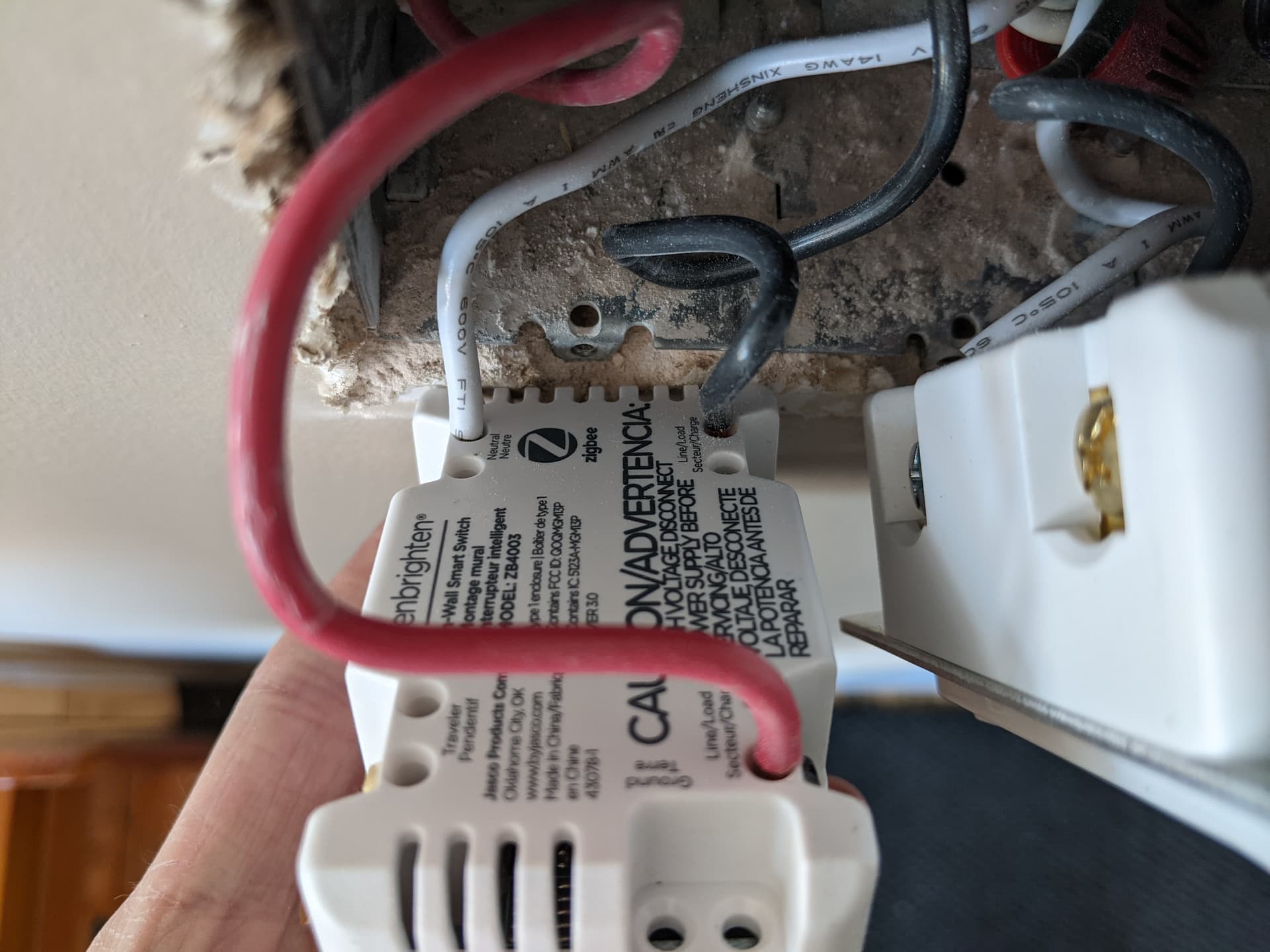
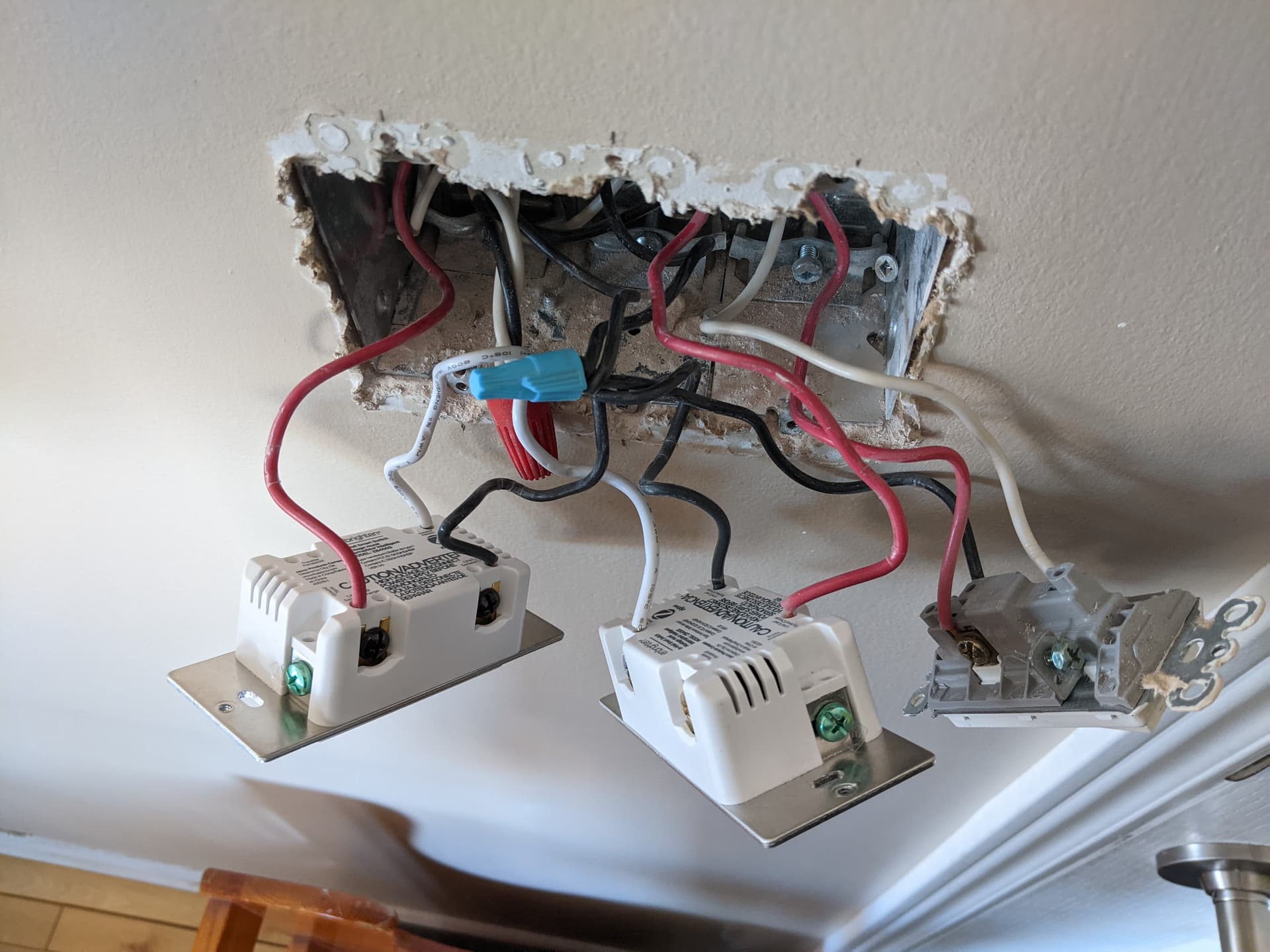
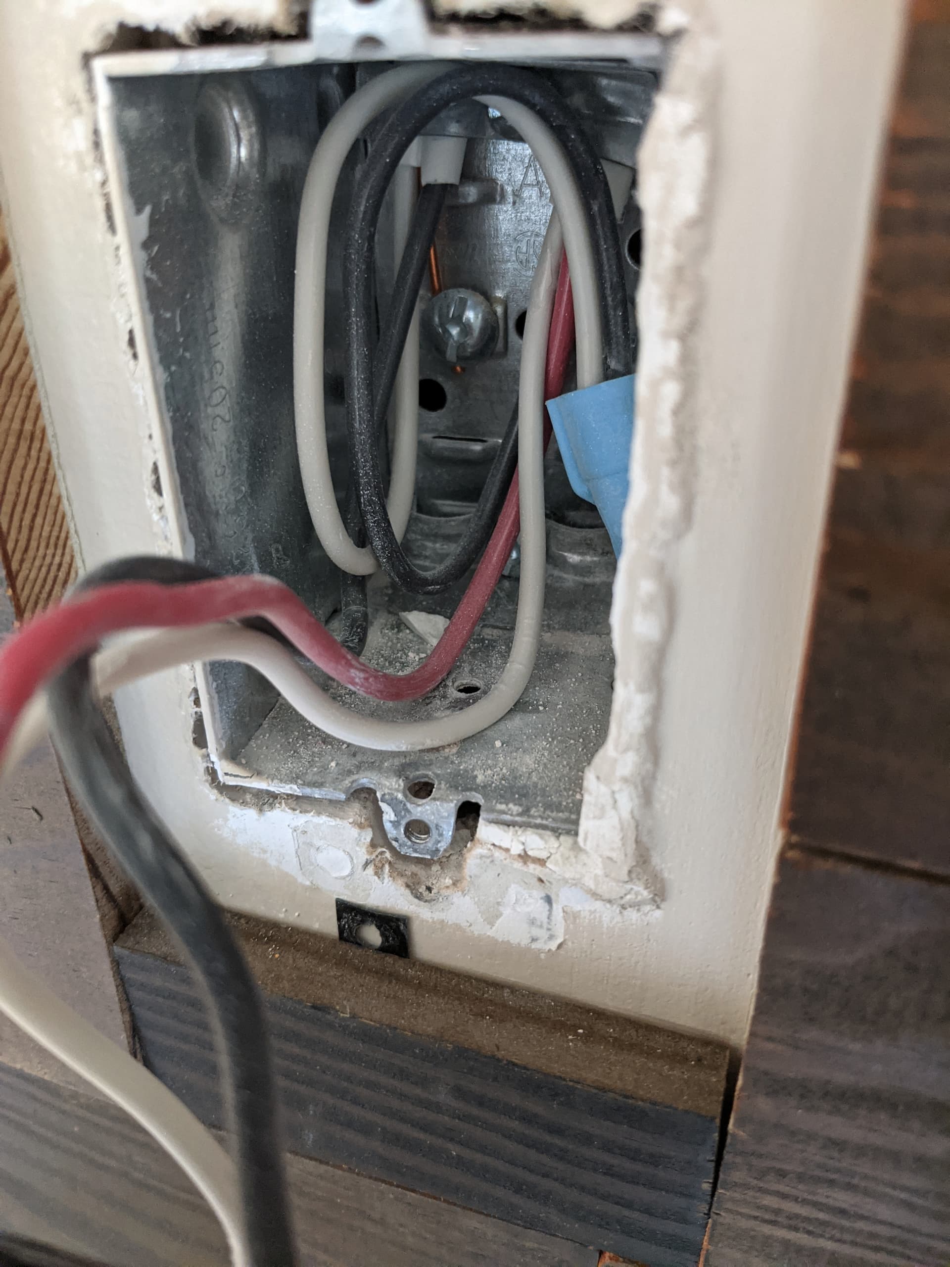
Switch 1:
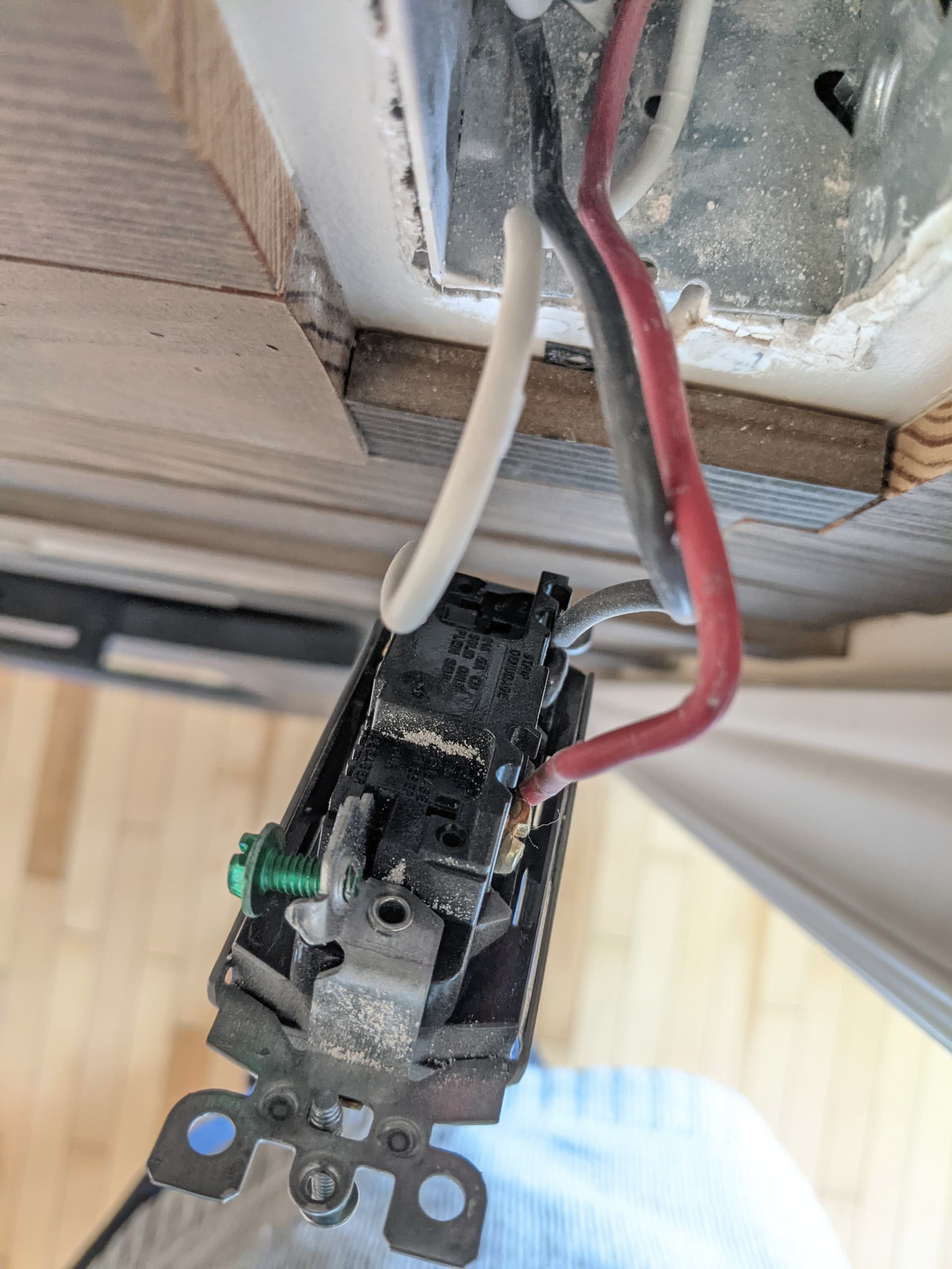
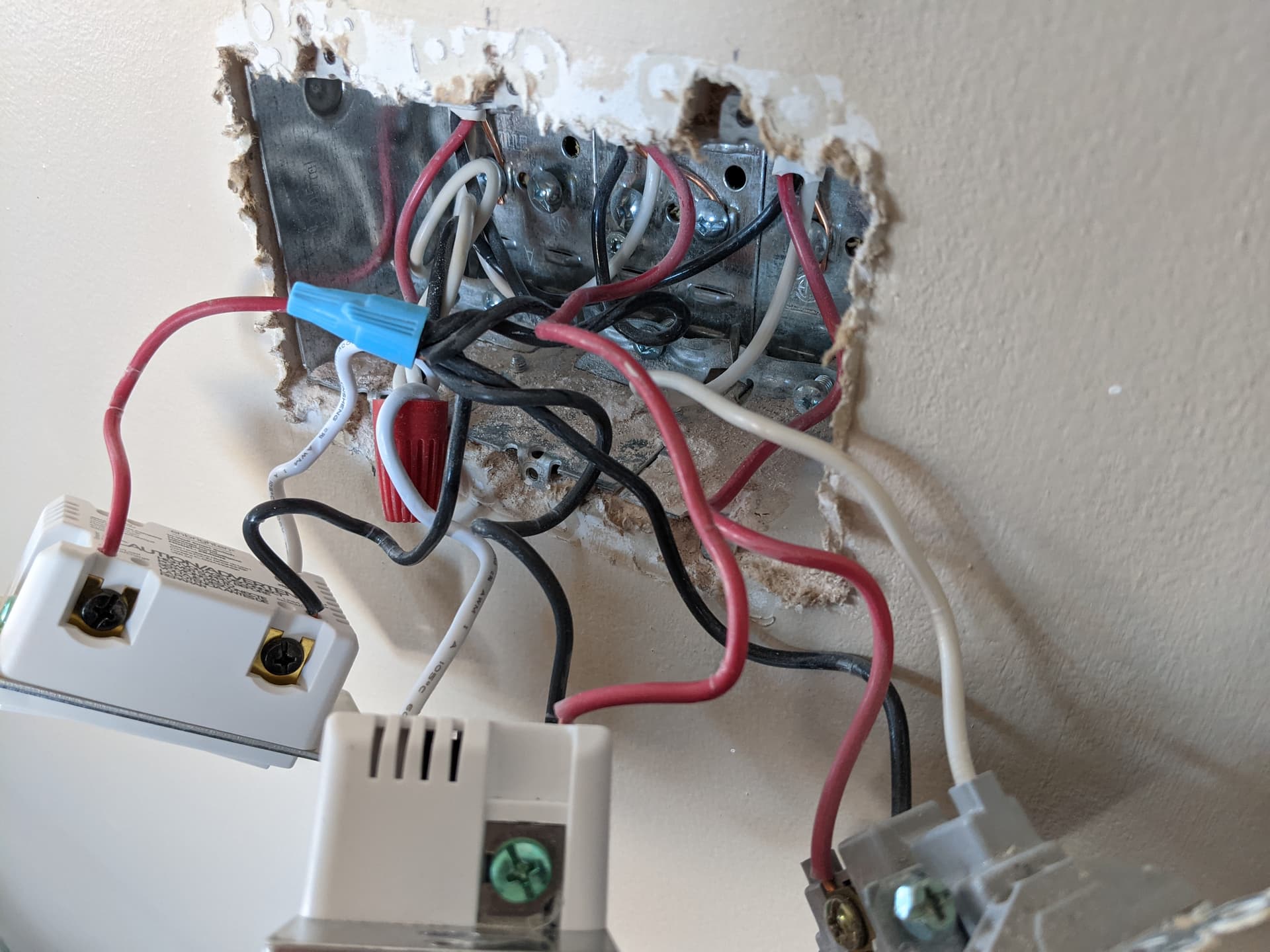
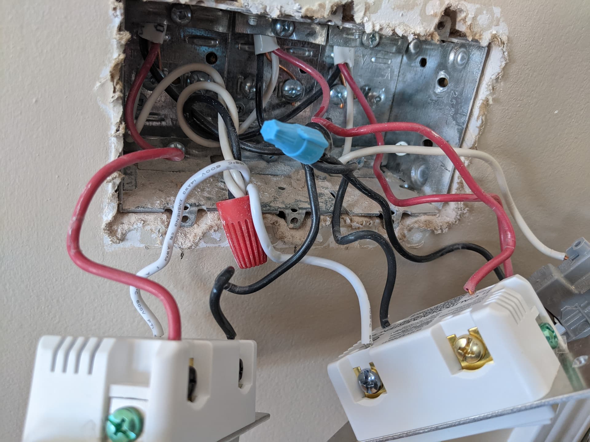
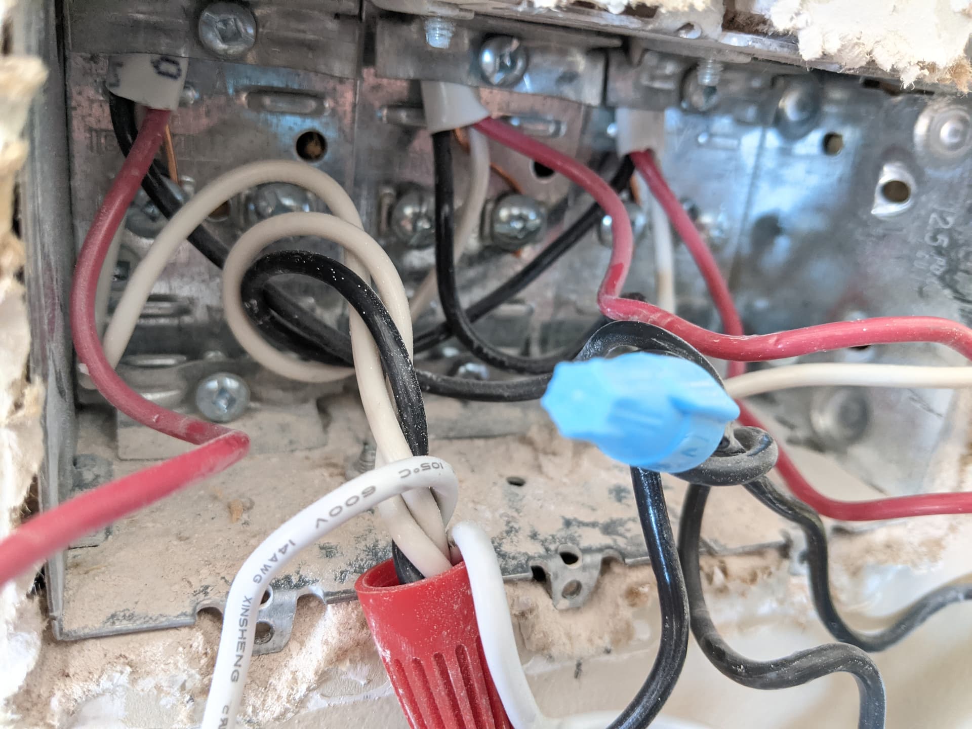
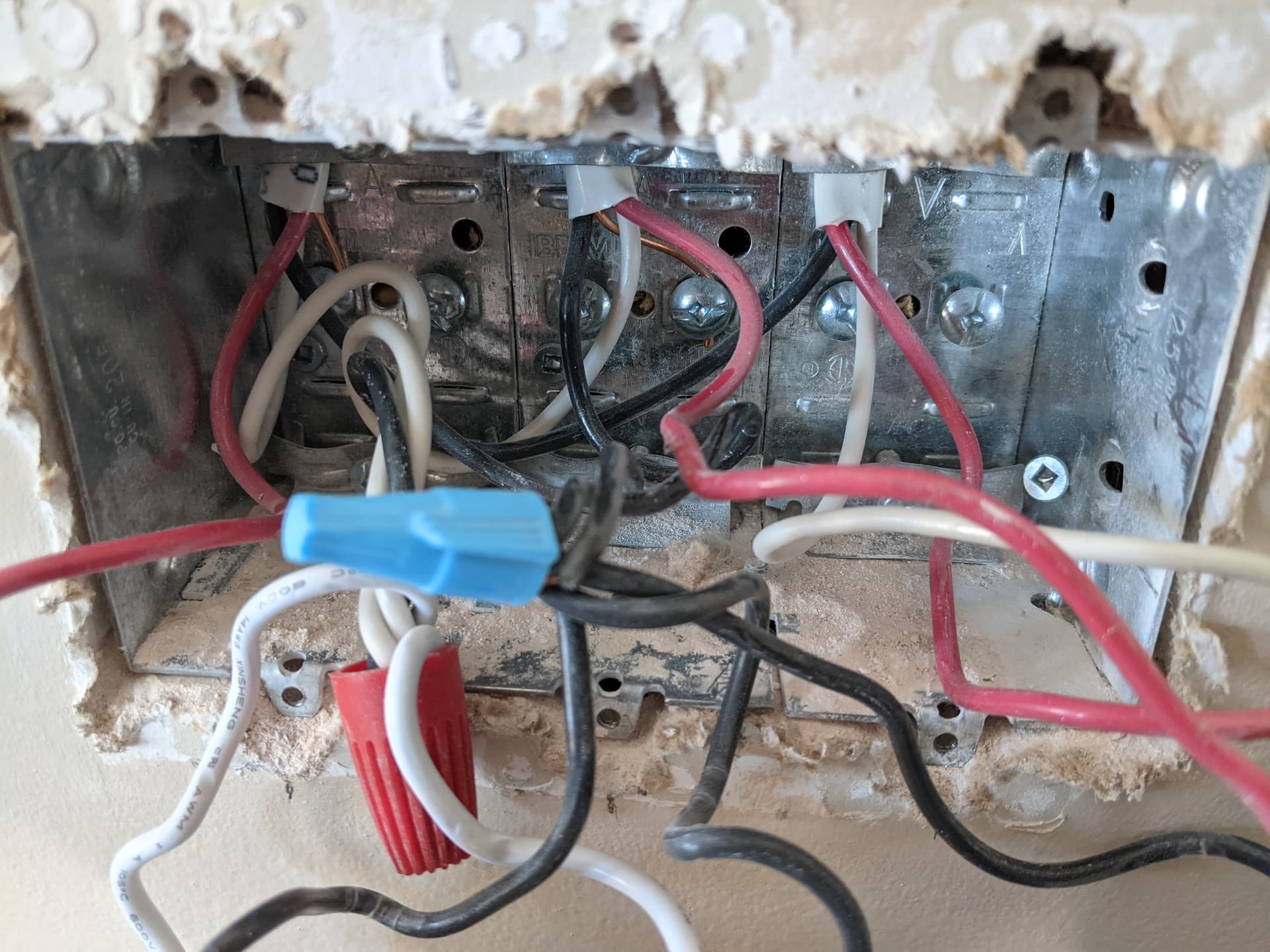
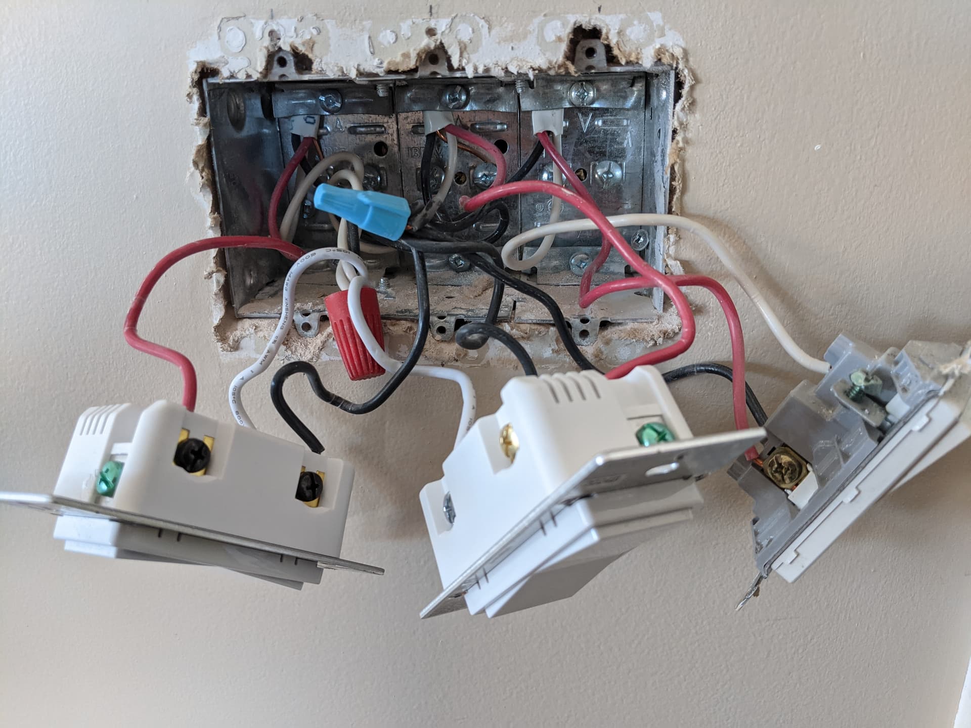
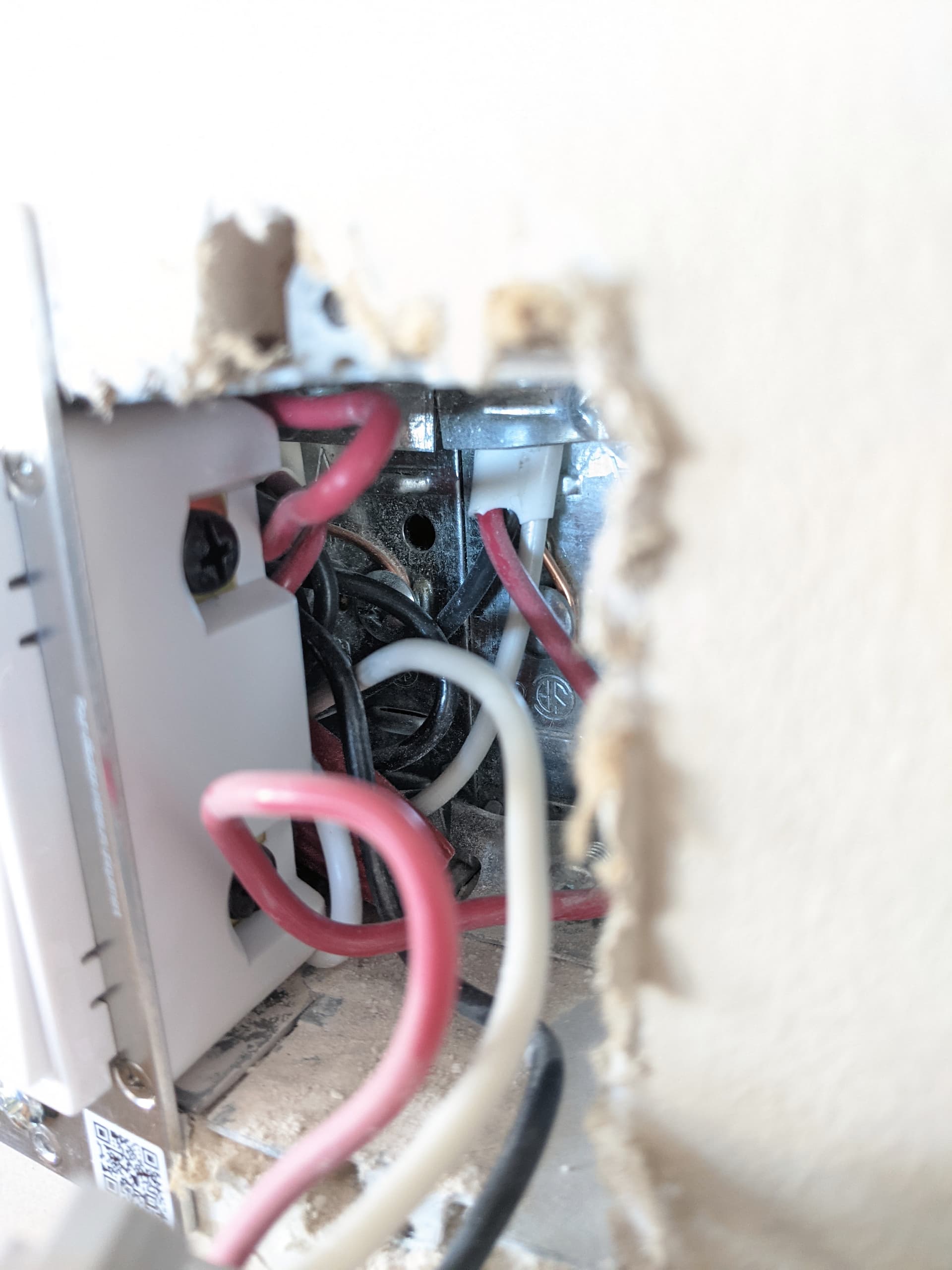
Switch 2:
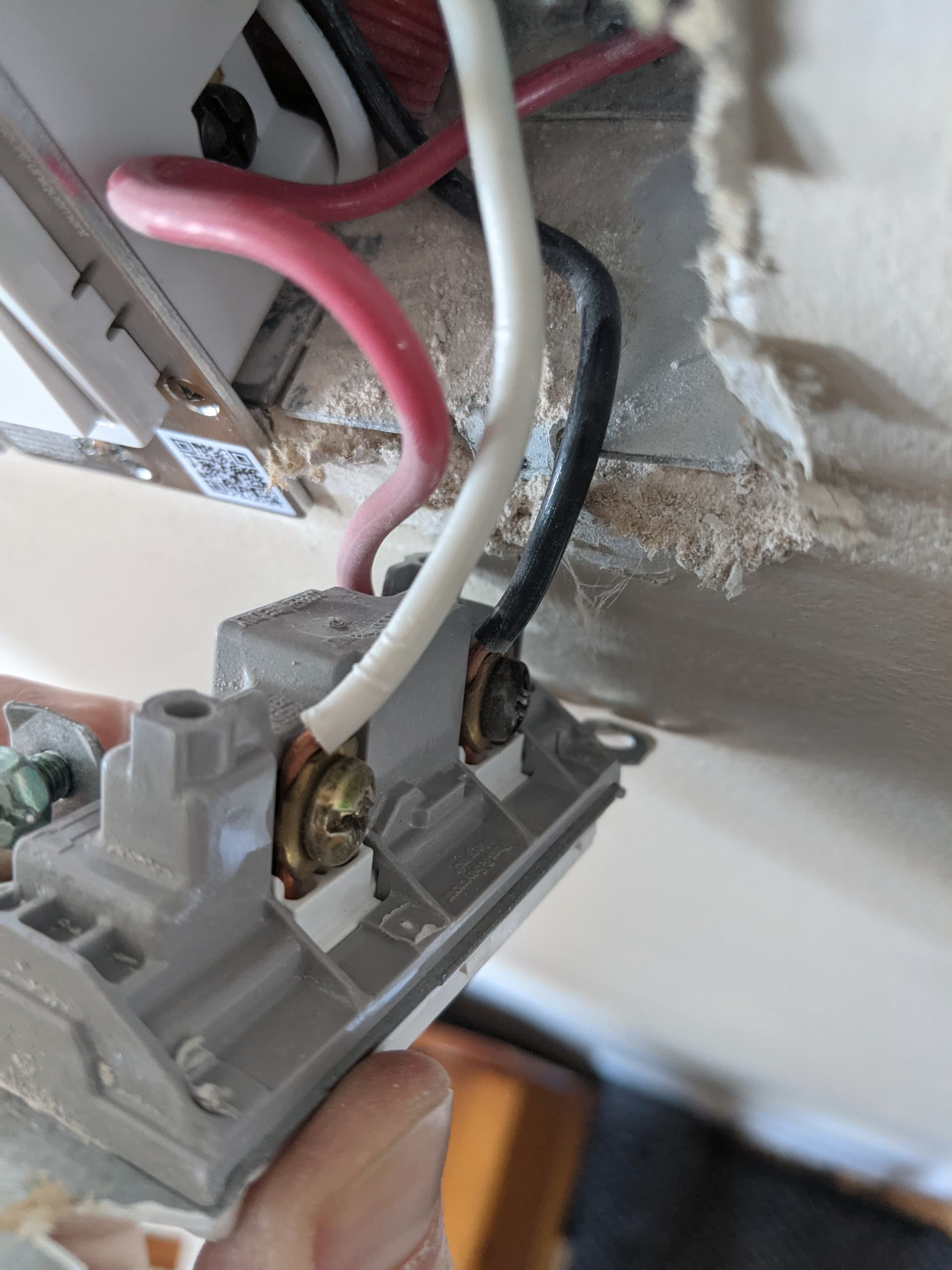
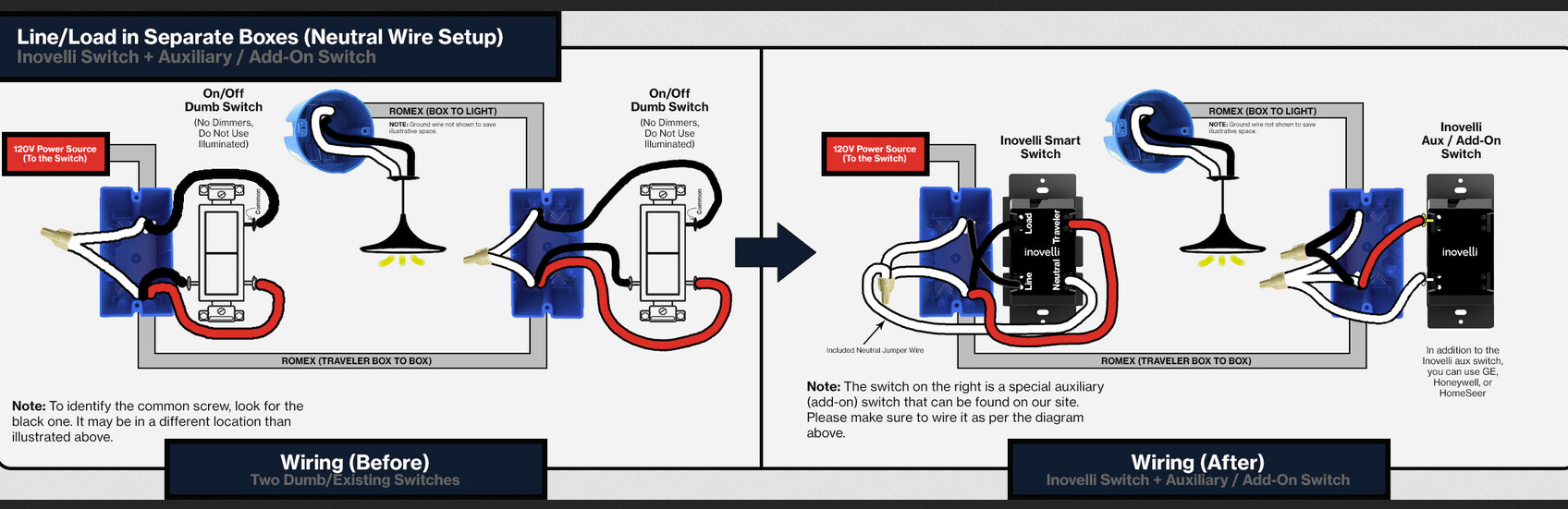
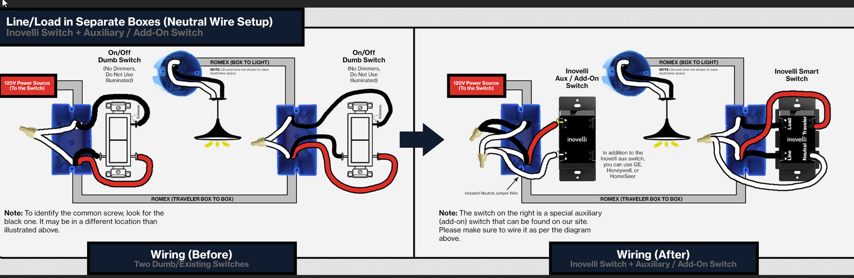
Based on what I see in my switch #1, it looks similar to the wiring of the switch connected to power source seen here:

The difference is that it’s not two white wires that connect together but a white and a black. Could it be that it’s just that wrong color wires were used in my setup ?
Yet, the wiring of my switch #2 does not look like in that schematics.
It looks more like in:

as I seem to only see 3 wires for that switch.
[EDIT] I had not seen it before, but maybe it’s rather that third schematics that seems to fit all my wires (except for the white / black mix):

Is there a way to validate that without unscrewing the fixture ?
I don’t intend to install that myself. For now all I want is to understand what I need to buy.
The thing is that if I can manage with only 1 smart switch that would be less expensive and I would not have to rewire things.
Thank you.