I have looked through the forums and found some things that are close to what I have but none exact. I have an extra black wire.
Probably 15 years ago the original switches were changed out for Insteon and a few years ago i went back to dumb switches.
The switch is a LZW31SN and the load is 4 can lights so it’s not simple to check the wiring there.
The two black on the left come out of separate pieces of romex with the white wire cut.
There is one strand of romex that connects between the boxes.
No grounds in the boxes.
No combination of wires will register 110 on a volt meter in either box so I assume it is coming from the light.
I have ordered an enbrighten 46199
Any advice for wiring would be greatly appreciated.
You should probably post some pics of your boxes with the switches pulled out as far a possible and so that you can clearly see into the box as well as the connections to the switches. If you have pictures of the dumb switches connected and working properly even better. Label the pictures right and left to identify the box.
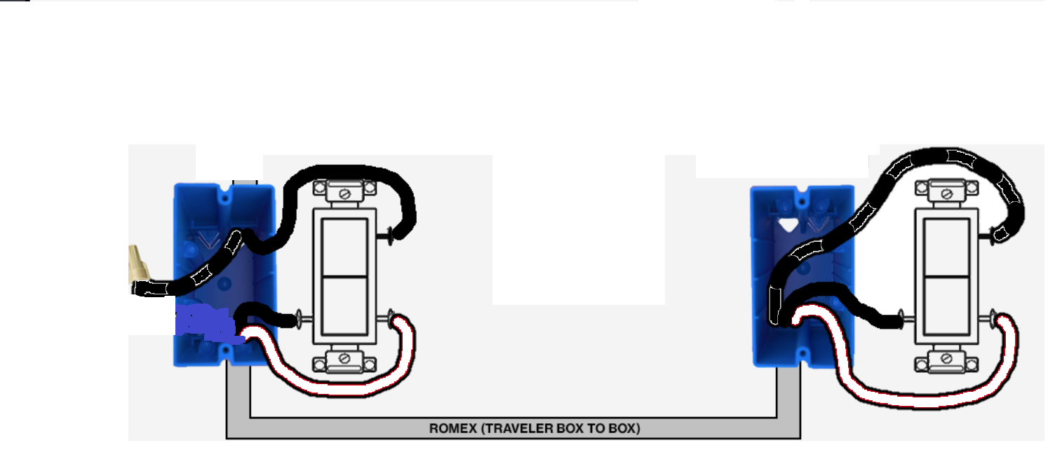
Without knowing what it looks like, your drawing is a bit confusing:
When you describe Romex, you need to state 2-wire or 3-wire (don’t count the ground). “Strand” doesn’t help much.
In the right box, is that a 2 or 3-wire Romex going into the box? A 3-wire typically has a white, black and red conductor. Your drawing has a white (edged in red?) a black and another black (with white markings?). Need to understand that better.
In the left box, it looks as if you have one 2-wire coming in the bottom and ??? Romex coming in the top? Is that two 2-wire Romex, both black with the whites cut from both? Not sure as one is black and the other is black with white markings.
You stated you have no grounds. Romex has a bare ground. Are the grounds there and cut short or do you perhaps not have Romex?
Are your boxes really plastic, or is that just for the drawing? If you have metal boxes/bx, that explains where your grounds are.
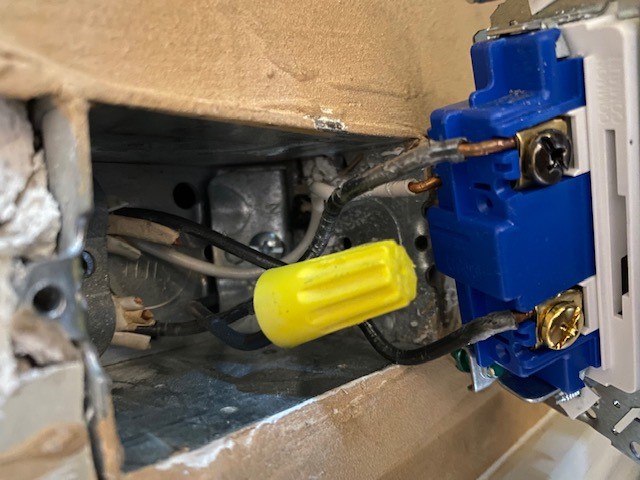
Right box is 2-wire Romex. The 2 wires in the right box go to the 2 wires in the left box. Checked with ohm meter.
Left box. The 2 wire pair goes to the right box. There is a 2-wire romex coming in that is wired to the common. The white wire and ground are cut short. There is another black wire coming from the bottom of the box that has a wire nut on it.
The grounds are there but cut short.
The boxes are metal
One additional note: The right box has a switch on the opposite side of the wall and I believe it has a neutral in it.
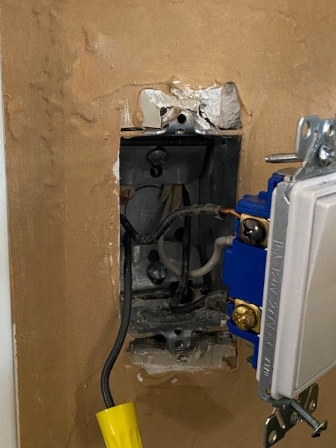
Pull that single capped wire up and out of the way and post another picture please. Need to see what’s behind it.
Based on what I’m seeing so far, and based on your testing that the two Romex in the right box go to the left box, more than likely instead of using a 3-wire, they used two 2-wires and cut one conductor short.
Your grounds are another matter. It’s frustrating to see work like that where the ground is cut short instead of properly grounding the metal box, which is hazardous, BTW
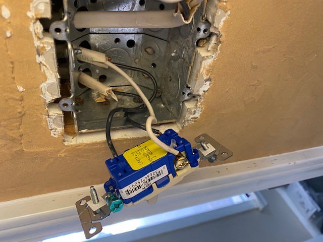
Left2
The two romex go up. The capped off black wire goes down. I loosened the strain relief and pulled out a little more slack on the bottom wire. The black and white wire in the 2-wire romex are definitely paired to the 2 on the other side, I ran a jumper across the room and tested them.
So you have two 2-wire Romex in each box using only three of the four conductors. Usually, there is a 3-wire between the two boxes, but it is not unusual to see two 2-wires run instead.
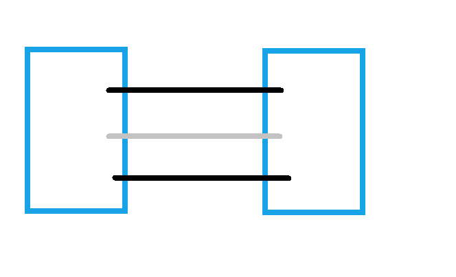
You believe that those three conductors are connected to each other box to box. While they might be connected electrically, they can’t be connected directly physically, as that just doesn’t make any sense. Basically, you would have this:
So those conductors may not be conducted as you think, because obviously you can’t just connect two switches together like that. They could still be going through another device and be electrically connected so when you continuity test them, you get the result you did.
Are you sure this is a 3-way? i.e only two switches. Could this possibly be a 4-way with a switch you are not aware of? (I know, sounds ridiculous, but we’ve had people find switches they didn’t know about in back of beds, etc.)
It’s weird that you can’t find a single hot in either box. If you are using a meter as opposed to a proximity tester, test between the black screws and the stub of the ground, if you haven’t already. Not sure how you tested previously.
Only the 2-wire romex one black one white run from left box to right box.
My best guess is that the line is connected to the common in the left box and the load is the common on the right box.
Without a neutral or ground, I don’t know enough to know if that is possible.
I am unable to check voltage from left box common to cut off ground until later.
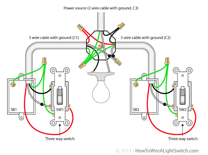
So if you truly have the equivalent of a single 3-wire in each box, and all three conductors of the 3-wire (in your case simulated by one and a half 2-wires) are connected to the three terminals on the switch, then the only wiring possibility I’m aware of is power to the light resulting in a non-neutral configuration with power to one box. It looks like this:
I think that is what I have. Seeing it drawn out really helps. My aux switch the 46199 came in today. Tomorrow I will verify the Left box common voltage to the ground and try to install. This is my first Inovelli and the forum support has been amazing. I look forward to installing more.
Ok good. Only you can determine what you have. Hard to do with certainty here.
But if you do have the configuration in the last drawing I posted, here is the solution. This has to be a dimmer since it will be a non-neutral.
In that drawing, a hot without a neutral gets sent to one box. The Aux switch goes in that box. The hot gets connected to the neutral terminal of the Aux (because in a non-neutral Inovelli config, that’s what it needs).
When you use an Aux, you need two conductors over to the Inovelli. So you will use the equivalent of the red and the white for that. Cap off the unused conductors.
The Inovelli goes in the Load box as a non-neutral. The hot and traveler come over from the Aux (via the light box). The Load is in that box.
Don’t forget to set the parameters for non-neutral and 3-way momentary.
I would hope a licensed electrician didn’t do that installation work. No wire strain reliefs, no grounding and cut off conductors.
If you have some slack pull enough into the boxes to strip more and get enough ground wire to connect them. I see an empty threaded hole near the wires, should be able to put a screw there to attach the grounds.
It also appears that the single gang has strain reliefs and one is clamping onto that black conductor directly. Strain reliefs should clamp onto the overall romex jacket.
Thanks for the help everyone, I am going to abandon this location for my switch until I can have an electrician look at it.
Voltage from the common to the bare ground was 88v and there was very little slack to pull in more romex.
The room on the back side of the switch is due a remodel this year, I can open the wall and see what’s going on then (more rewiring then also).
I’ll start looking at other switches I want to replace while I’m waiting and make a list of repairs I need.
The house is only about 30 years old but in a rural area that still doesn’t have electrical inspections today.