I have an LZW30 that I was hoping to use with a dumb switch. Then I determined that there is no Neutral in the same box as the Line. But there is neutral in the box with the Load. I couldn’t find a diagram with this configuration. Is there a way to wire this?
Don’t take this wrong, but I don’t think you have what you think you have. You’ll need to diagnose further.
If you truly have a non-neutral, then the power is coming from the light without a neutral. The the only place the neutral is connected is at the light so there isn’t a neutral at either switch box. The only possibility would be that you are referring to a neutral unrelated to this switch leg.
Also, the only way you can have a 3-way line and load in separate boxes is with a neutral configuration. In a non-neutral situation, the line and load are in the same box because the line comes in on one of the 2-wire conductors and goes out as the load on the other 2-wire conductor.
You say that Box 1 is a line from the house. Do you know that for a fact or are you saying that just because it’s hot. If it really is coming from the house, where is the accompanying neutral? House feeds don’t show up on one wire.
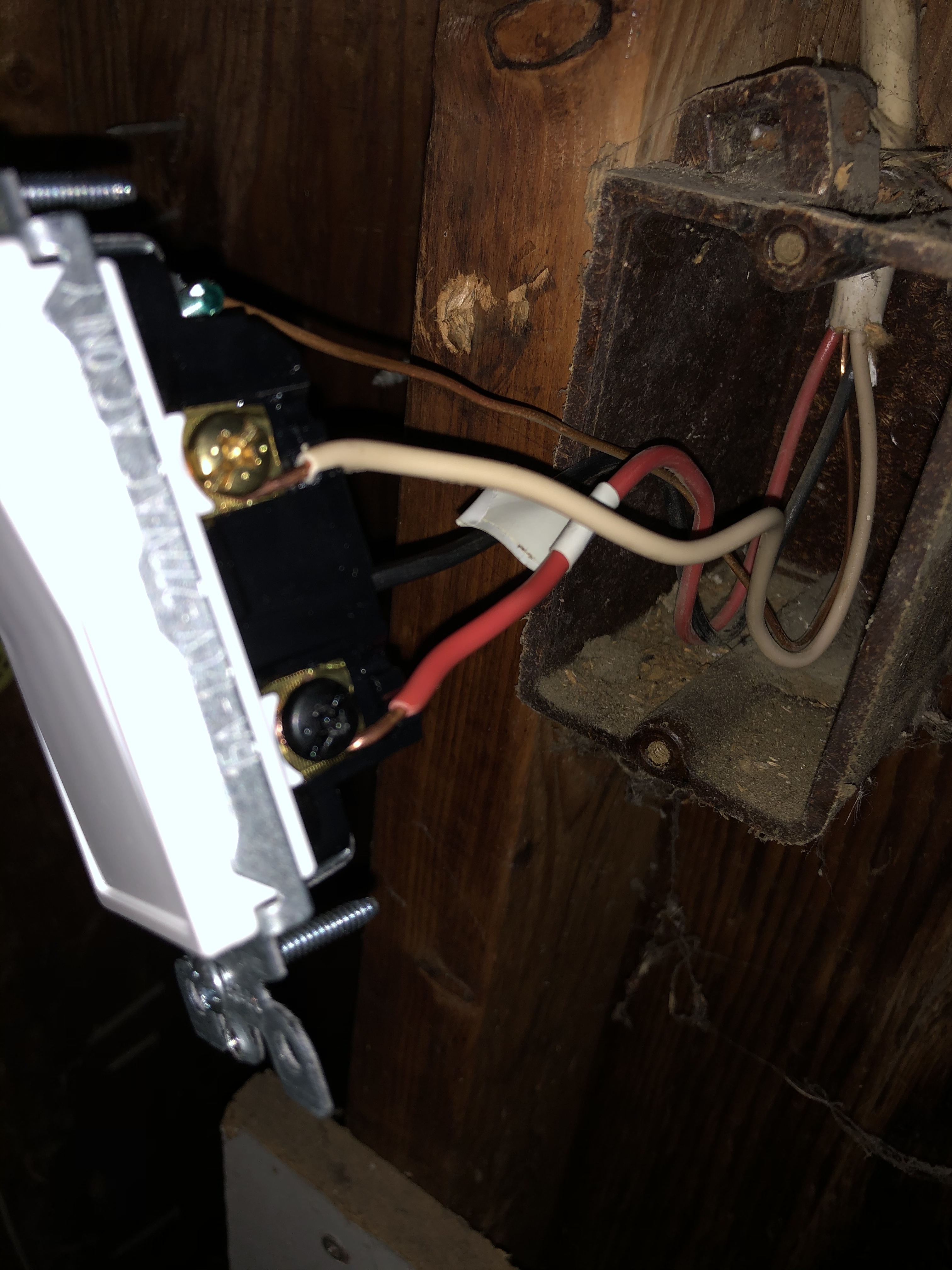
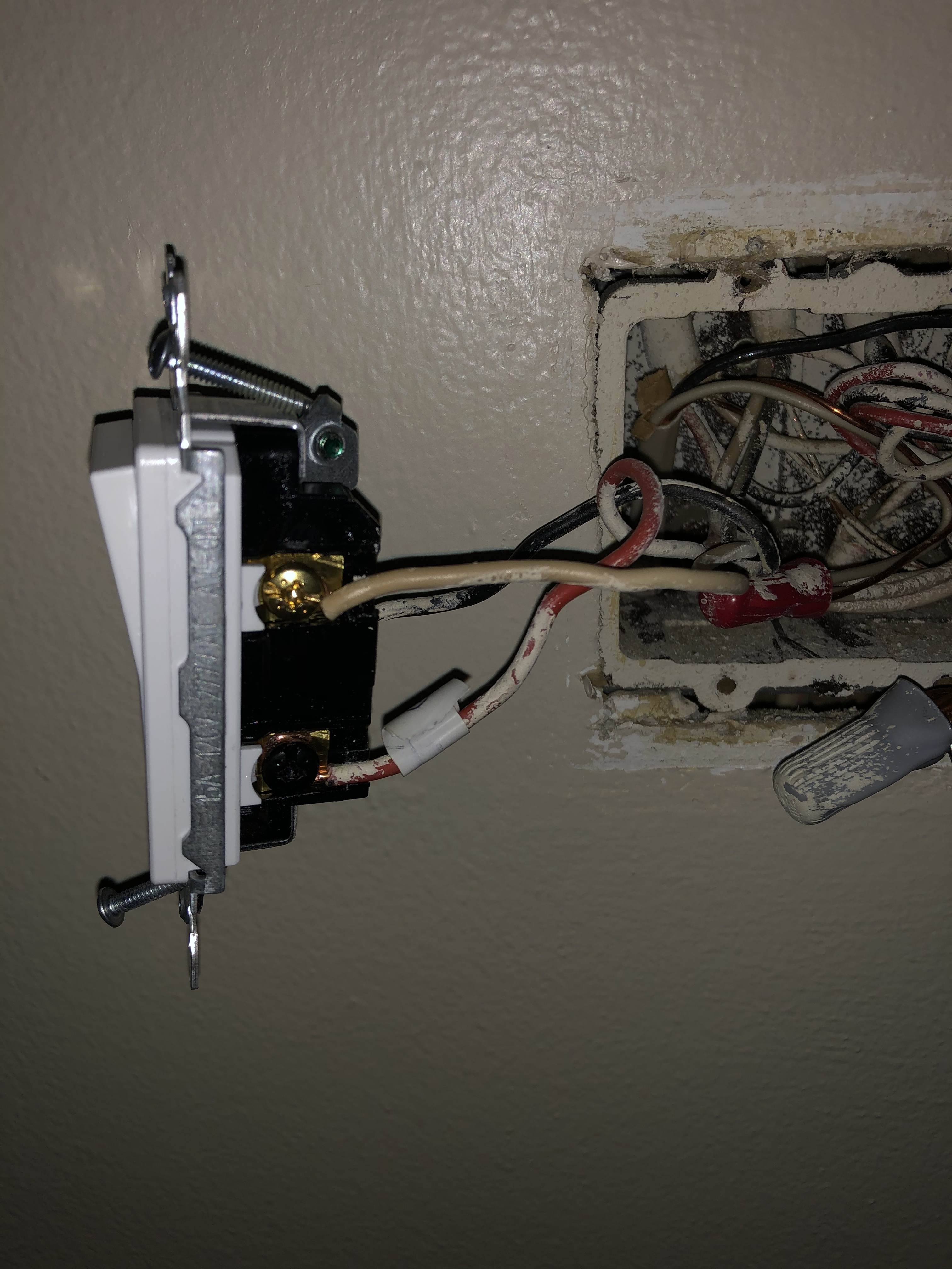
Here are pictures. I took the wires apart from the switches and tested with a multimeter. Box 2 had no voltage at any wires when all disconnected. Box 1 had 120 at the red wire.
Box 1. Red is the only wire with 120 when all disconnected.
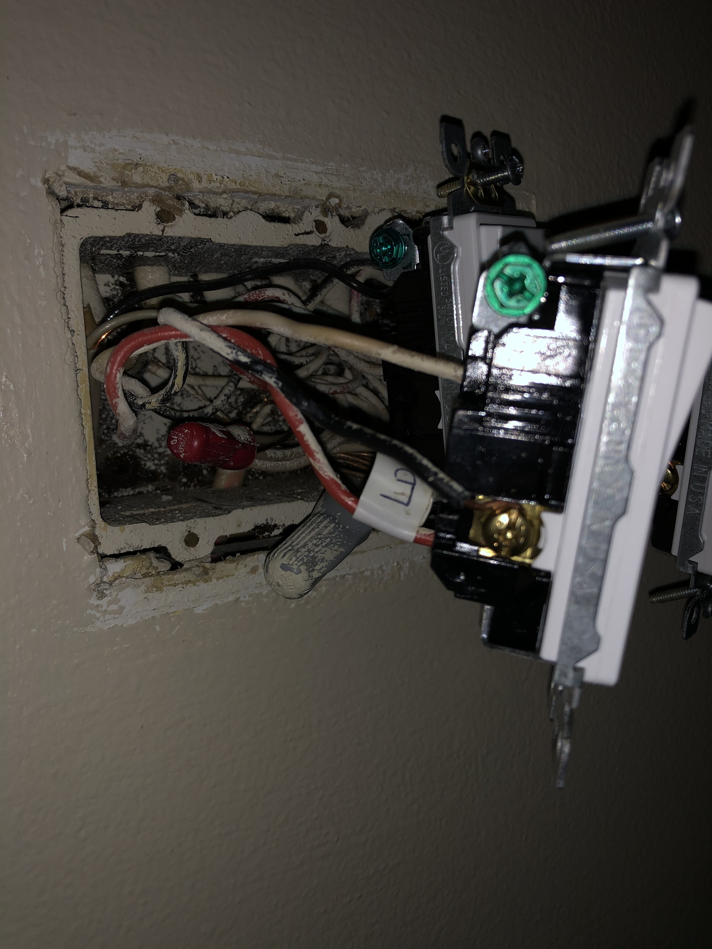
Box 2. Has neutrals in a bundle. I connected all 3 wires together in box 1 then tested box 2 wires separately. Black and white each had 120. Leaving red as the load.
Ok, so in box 1 I can see that all three wires connected to the switch are from one 3-wire, as that’s the only Romex I see in the box.
In box 2, it’s tough to tell. Do all three conductors connected to the switch belong to the same 3-wire Romex? I can’t see into the box well enough to tell.
Ok, sorry to be asking so many questions but you have a lot of stuff going on here.
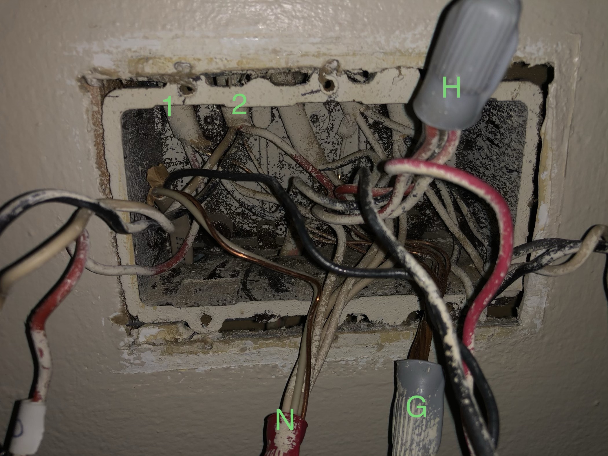
So both Romex partially connected to the switch are 3-wires? Fill in the blanks below because I can’t see the switch. Also, there is no bundle C in your picture. Let’s not use terms like “Load” and “Line” and all that stuff. They just whack out my thought process and if we knew what they were for real, we wouldn’t be here, lol.
On the switch connections, specify brass or black screw. There are 2 brass screws but just saying brass is fine. The most important is knowing which one is connected to the black.
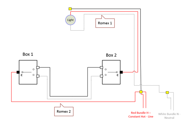
Romex 1 - 3-wire:
Black is connected to Bundle H with the Reds
White is connected to Bundle N with the Whites
Red is connected to switch’s ____ terminal
Romex 2 - 3-wire
Black is connected to switch’s ____ terminal
White is connected to switch’s ____ terminal
Red is connected to Bundle H with the Reds
If any of the above is wrong, let me know that too.
What is this powering? A single light, maybe. Can you get at the box if need be?
Ok, so to recap . . going to have to draw this out. You have an extra conductor which is probably sending an additional hot down the line. Just have to figure out which one that is.
Please double check this:
Box 1:
Romex 3-wire:
Black is connected to the switch’s brass terminal
White is connected to the switch’s brass terminal
Red is connected to the switch’s black terminal
Box 2:
Romex 1 - 3-wire:
Black is connected to Bundle H with the Reds
White is connected to Bundle N with the Whites
Red is connected to switch’s black terminal
Romex 2 - 3-wire
Black is connected to switch’s brass terminal
White is connected to switch’s brass terminal
Red is connected to Bundle H with the Reds
So at this point my best guess, pending some confirmations, is that your power w/neutral starts in Box 2, with the Line and Load in the same box. This means that the switch is powered from this box. It also means that the Romex to the light is in this box too. If that’s correct, this is where the Inovelli will go.
The thing that is confusing is that in a Line/Load in the same box, typically you will have 2 “outgoing” Romexs, a 2-wire going to the light and a 3-wire going to the other switch. In your case, you have two “outgoing” 3-wires. That’s not all that unusual, as the third conductor to the light can be used to send a constant hot downstream. It’s just a matter of understanding the original electrician’s logic.
In the mean time, a voltage measurement is in order. Do you have a meter? In Box 2, pop the wire nut off bundle H which has a red and a black from this switch (right?). Test for voltage between that bundle and the bare copper ground (or that bundle of whites if you want). I would expect a constant 120V. Do this test with BOTH switches in different positions so that you can confirm that the red/black bundle is ALWAYS 120V regardless of any switch position. I think that’s going to be the case, but please confirm.
No problem. Just check that red bundle for now. After you confirm, I’ll tell you what I think you have with a diagram and ask you to check a couple things to confirm. One of those involves the ceiling box, so hold off on the ceiling boxes until you see what I’m thinking.
Ok, so here is what I believe you have. This is a neutral installation that starts in Box 2. Both the Line and Load are in Box 2. Power is fed to the leg by the bundles of reds. You have already confirmed that the bundle is a constant hot.
The constant hot is passed to Box 1, which is the accepted technique Line/Load in the same box, via the red on the 3-wire (Romex 2) between the two boxes. In Box 1, the red carrying the constant hot is connected to the black (common) terminal. I think you tested this before, but in case you didn’t, test that red in Box 1 with it REMOVED FROM THE SWITCH and WITH THE SWITCH IN BOX 2 IN BOTH POSITIONS. The red should be a constant hot.
So in Box 1, the hot comes back to Box 2 switched via the black and white travelers on Romex 2. It is then switched to the light via the Red of Romex 1.
Romex 1 to the light is a 3-wire. The black is also attached to the constant hot red bundle, presumably to send a hot down the line. It doesn’t factor in here.
The next check you should do is using a meter, test between the black common terminal in Box 2 and the bare ground. This should be a switched hot, so as you toggle the two switches that power should go on and off.
The last double-check is a the box… the first one if you can find it. I would expect to find a 3-wire there, with the light powered by the red and the white neutral. The black, which is always hot, may be connected to a 3-wire which goes to the next light.
So see if this makes sense to you. Test or confirm the unattached Red in Box 1, the common terminal in Box 2 and the wiring at the light. If it looks good, then you’re ready to adapt the Inovelli into Box 2.
Ok, so basically your saying the the red from the switched is the switched hot to the light (at least initially) and the black is just providing a constant hot down the line (at least initially).
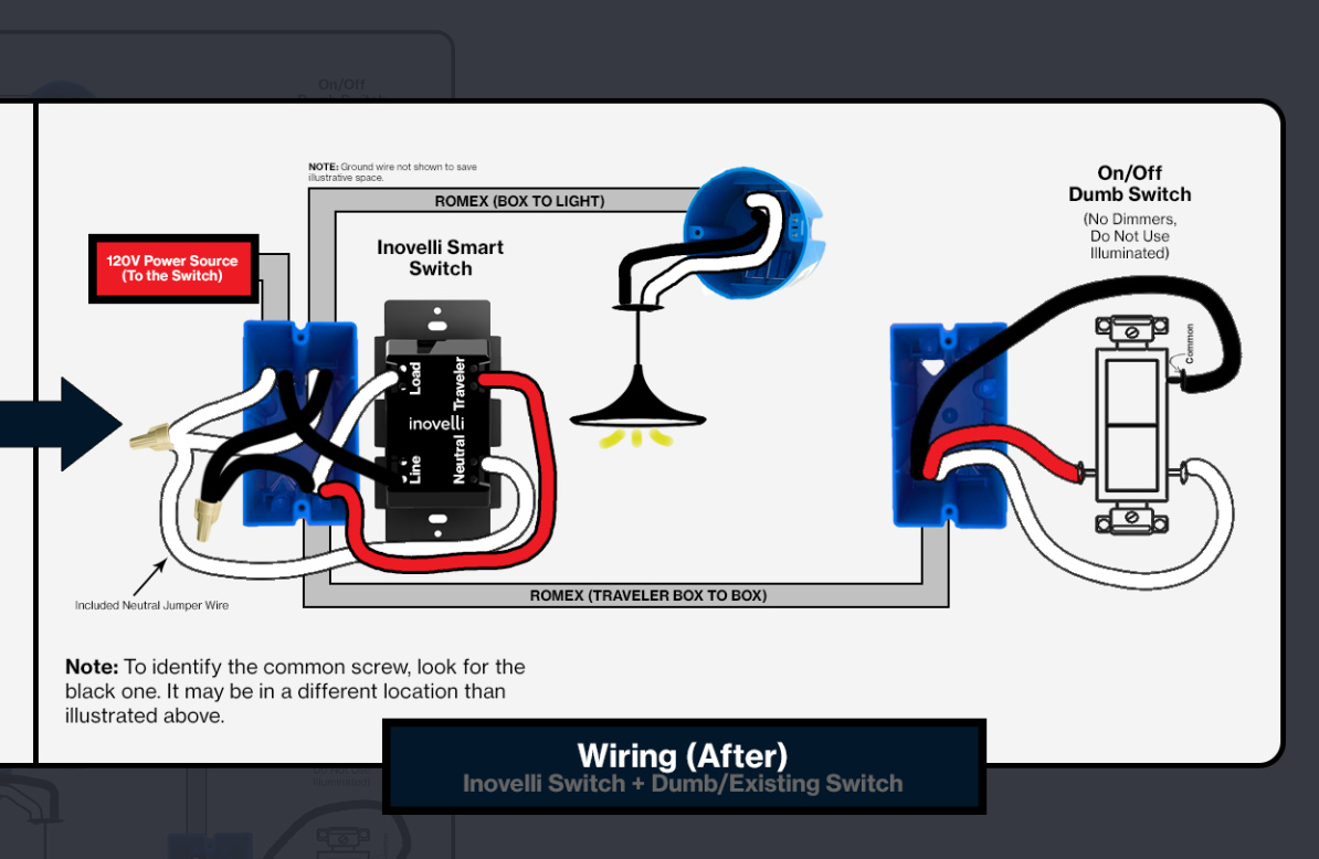
So you neutral config with Line and Load in the same box (Box 2). So the Inovelli goes in Box 2. Use the diagram below. The only difference really is that your constant hot is a red, not a black.