Have everything set up and working except the left switch in Diagram A is showing no signs of power at all. I will say I followed the diagrams exactly except for how the neutrals are wired for the left and the right in Diagram A so if that is the culprit can someone tell me exact White #s to switch from my current wiring.
Diagram A
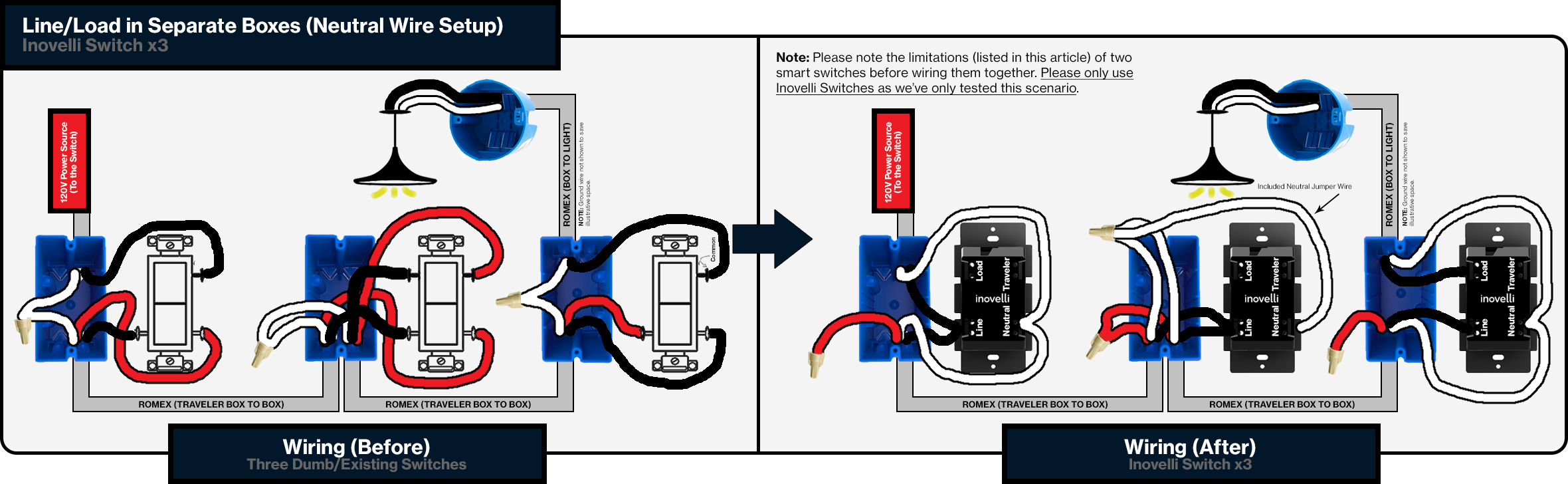
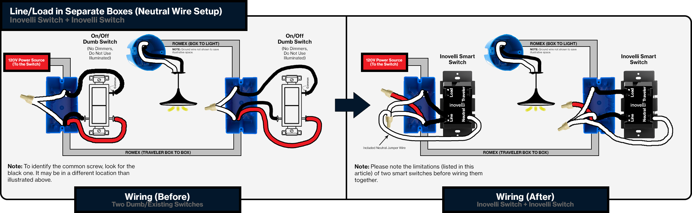
Diagram B
I have two two-gang boxes that are of mention
BOX 1
Top Left 1 (Black #1, White #1, Red, Ground)
Top Left 2 (Black #2, White #2, Ground)
Top Middle (Black #3, White #3, Ground)
Top Right (Black #4, White #4, Red, Ground)
Bottom (Black #5, White #5, Ground)
Black Capped (Black #2, Black #3, Black #5)
White Capped (All # Whites)
Switch #1 (Black #1 in Line, Black wire in Line to black capped, inovelli provided neutral line to white cap)
This switch is part of a 4 way and what I believe is the left switch from the diagram A
Switch #2 (Black #3 in Line, Black wire in Line to black capped, inovelli provided neutral line to white cap)
This switch is part of a 3 way and what I believe is the left switch from the diagram B
BOX 2
4 separate entry points across the top
Top 1 (Black #1, White #1, Red, Ground)
Top 2 (Black #2, White #2, Ground)
Top 3 (Black #3, White #3, Ground)
Top 4 (Black #3, White #4, Ground)
Bottom (Black #5, White #5, Ground)
Black Capped (Black #2, Black #5)
White Capped (All # Whites)
Switch #1 (Black #1 in Load, Black #3 in Line, inovelli provided neutral line to white cap)
This switch is part of a 4 way and what I believe is the right switch from the diagram A
Switch #2 (Black #4 in Load, Black wire in Line to Black Capped, inovelli provided neutral line to white cap)
This is a simple single pole switch
Can someone help me get power to Switch #1 in Box #1. I am super confused how it doesn’t have power since I would think it is directly wired to the master power line.