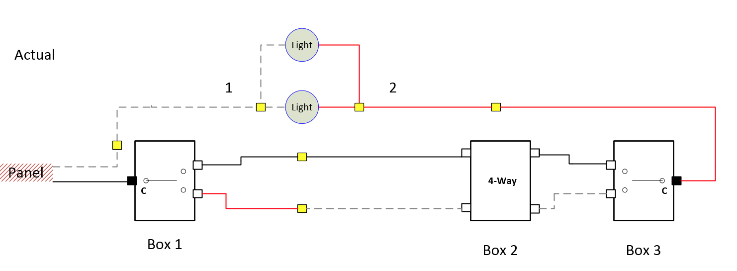
@Bry Your diagram exactly matches what I (tried to) lay out in my post, as far as where it would make sense for the wires to be going. And the light still having power when all wires in box 2 are disconnected also confirms that.
The only difference is that, if you want to match all the colors, the hot leads of the two lights should be black, not red.
Looking at your diagram makes me more confident that either of my proposed wiring plans will work.
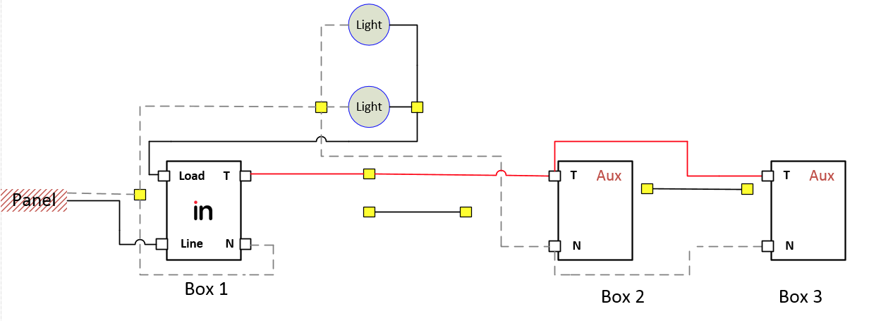
I’m trying to think of a way to put the inovelli switch in box 2. I think if you want to do that you’d have to do a non-neutral setup, which would work like this:
Aux switch in box 1. Cable from box1 to light carries Line (black), Neutral (white) and the traveler (red) from the aux switch. Connect the neutral terminal of the aux switch to line, as that seems to be how the aux switches work in a non-neutral setup.
In the light box, connect W1, W3, and fixture white (neutral). Connect R1 to R2 (traveler). Connect B1 to B2 (line). Connect W2, B3 and fixture black (load). Put a piece of colored electrical tape (any color except green or white) on wire W2, to indicate that it is not a neutral.
In box 2, identify which of the two cables comes from the light, and which goes to box 3. Connect both blacks to the line terminal, and both reds to the traveler terminal. Attach the white from the light to the load terminal (add colored electrical tape to the wire). Cap off the white from box 3 (you won’t use it).
In box 3, connect red to traveler and black to neutral on the aux switch.
I think it is provably impossible to put the inovelli switch in box 2 unless you use a non neutral setup, since all four terminals would need to be carried to the light. Line and neutral must come from upstream; there’s nowhere else they can come from. Load must go from the switch to the light. The aux switch in box 1 must be able to connect to the traveler terminal, which it can only do by going through the light box. So that means we need 4 wires running from the light box to box 2, and we only have 3.
Do not use the grounding wire as a fourth wire. It is illegal and unsafe.
I’m now pretty confident that this is a complete list of options that would work:
- Inovelli in box 1, dumb 4-way in box 2, dumb 3-way in box 3, no wiring changes except in box 1
- Inovelli in box 1, aux switches in boxes 2 and 3, wired as I described in a previous post
- Inovelli in box 2, running in non-neutral configuration, aux switches in boxes 1 and 3, wired as described in this post.
- Inovelli in box 3, running in non-neutral configuration, aux switches in boxes 1 and 2. The wiring would be very similar to option 3, except that you’d use the white wire running between boxes 2 and 3, instead of capping it off. If you’re interested in this I can flesh it out.
- Two inovellis, both running with a neutral, one each in boxes 1 and 2, with either a dumb 3-way or aux switch in box 3. I’d probably recommend the aux switch. One inovelli switch would be wired to the load, and one would operate in smart bulb mode, associated to the first. You have enough wires to have either box 1 or box 2 be wired to the light. If you’re interested in this I can flesh it out.
I wouldn’t recommend using the non-neutral configuration since you have other viable options. If you’ve got a good direct straight-line path between boxes 1 and 2 for the zwave signal to travel directly, and a spare inovelli switch, the two inovelli option could be really nice. I’ve got one of my three ways set up like that, and with the right settings, it feels just like a wired aux switch, but I get scenes and notifications on both ends.
I would not recommend associations if there isn’t a path for a strong zwave signal between the two switches. The association messages go directly from one switch to the other without passing through the hub, so that’s the path that’s relevant.