Box 2
Traveler Set to Box 1 (B/W/R)
Traveler Set to Box 3 (B/W/R)
Box 3
Traveler Set to Box 2 (B/W/R)
Somehow/where the load is coming off the traveler set between Box 2 & 3. I’m trying to avoid taking down the two light fixtures to look underneath the mounts.
Planning to use LZW31-SN, neutral config
Any suggestions on how to set this one up? If needed, I’ll start to mock up a better diagram)
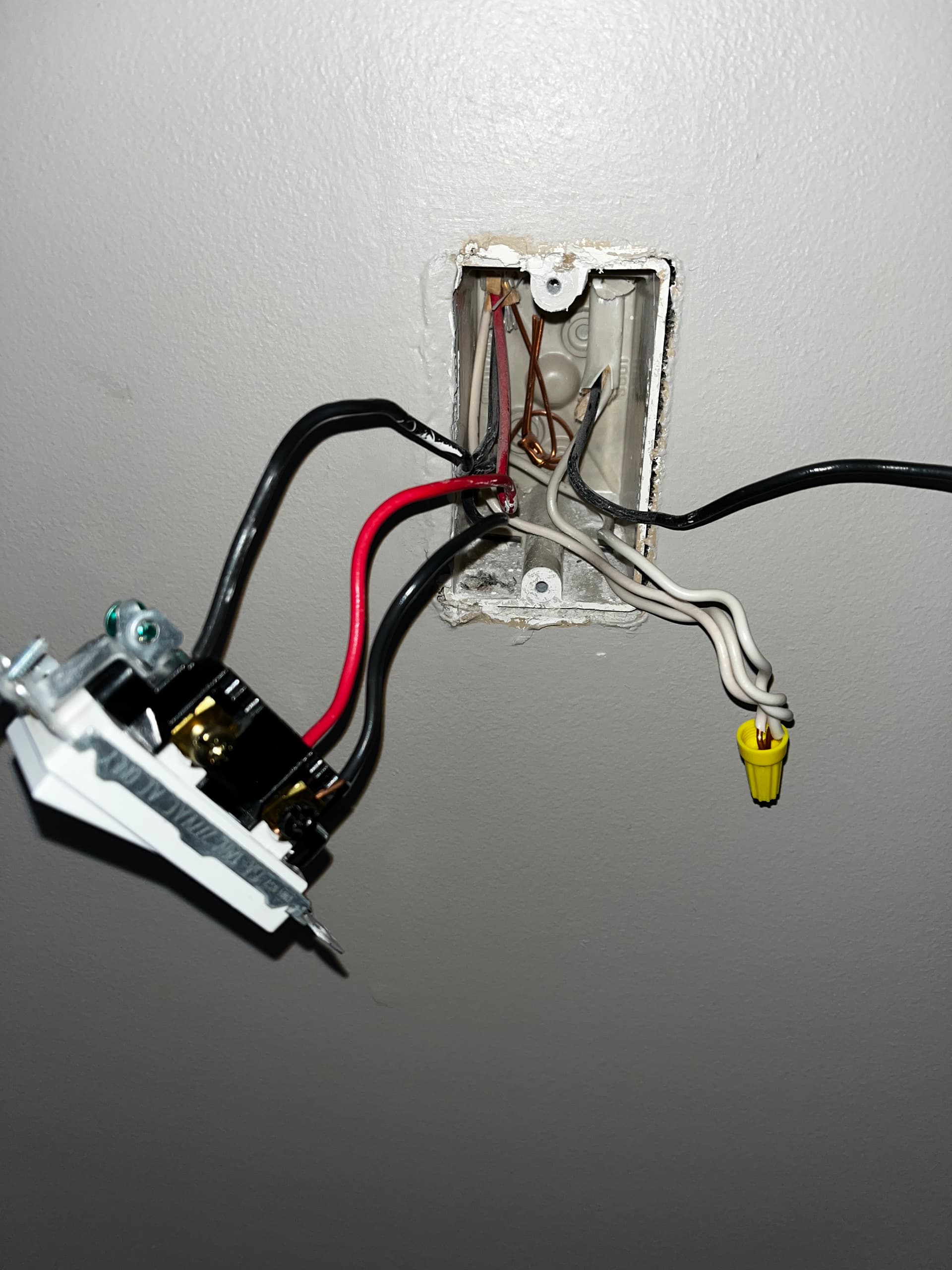
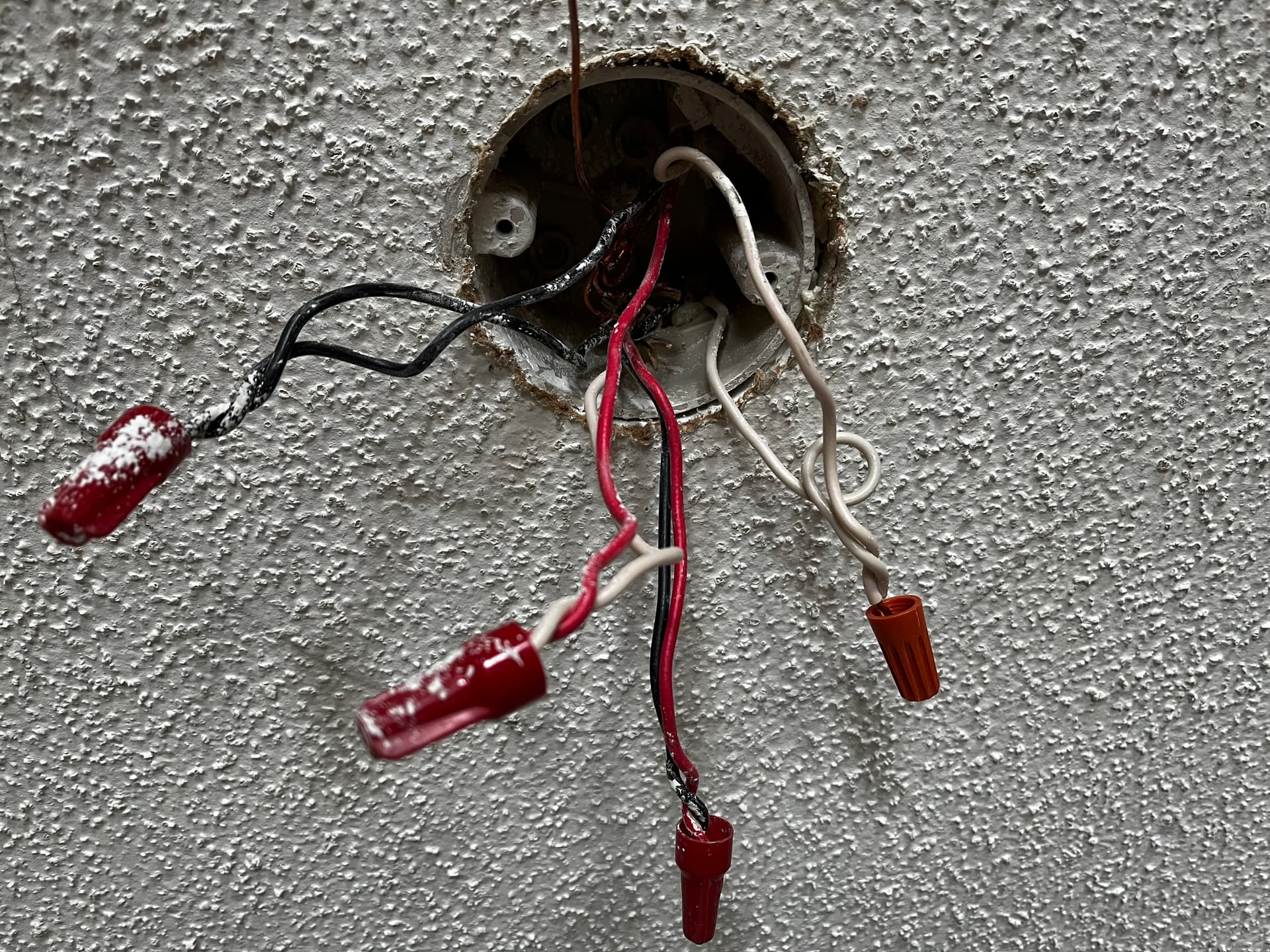
Little tough to see into box one. There are actually three Romex in there, right? One 3-wire and two 2-wire? I’m guessing that because I see three whites that are bundled.
Also, what’s up with that Romex at the top right of the box 1? The black is out of the picture. Capped off?
Correct, I tried to call out only wires for that light . The black out of the pic in BOX 1 is linE that goes to another room.
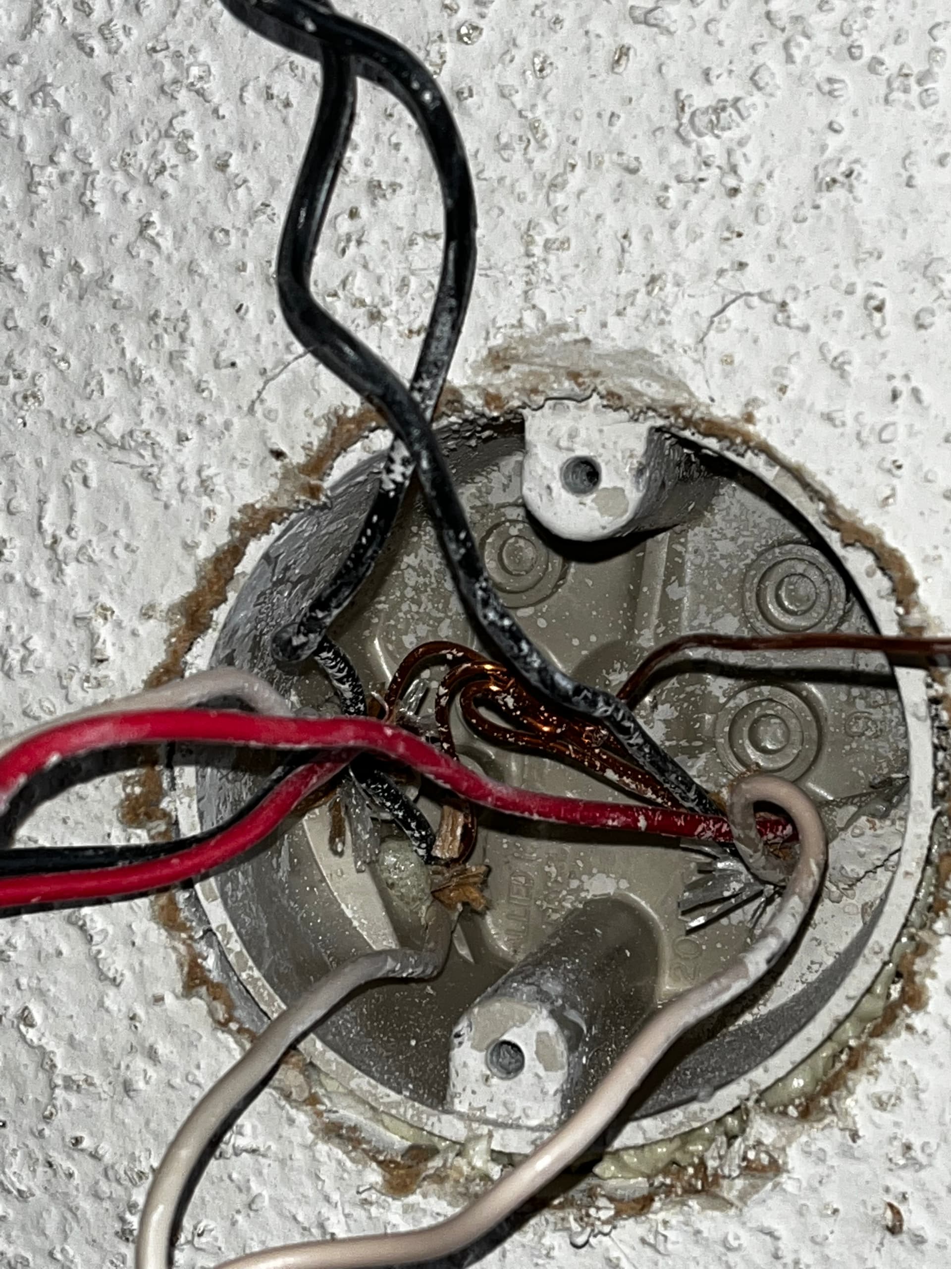
In Box 2, there are 6 sets going into the box. Only b,w,r on the far left two sets connect to the switch, with the reds capped together. When I take the black out of the bottom one in box 2, connectivity to box 3 is lost, but load still works. When I take the white out of that traveller of that same set off, load drops.
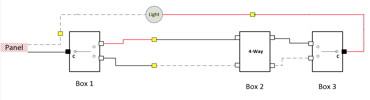
Interesting. It might be something like this, but you’ll have to test to see if it makes sense.
I’m feeling like the load is coming out of Box 3 on the common screw since the line is being fed to Box 1. (Normally you’d have a 2-wire in box three used to send the switched hot and a neutral to the light, but that’s not obviously happening here).
Try testing the bundled red in the 4-way switch box. Using a meter, test between the red and the ground. I’m thinking that it will turn on and off as you flip the switches because that is the load on the way back to the light.
I happen to have 2 enbrighten/jasco (46199) aux switches available. Dimmer isn’t necessarily needed on this, using it more for the red series led notifications with Hubitat and red series on/off were out of stock. But since I’m already 1/2 way there…
Edit: Also, can I ask what sw did you use for your diagram?
EDIT: I don’t think you will be able to do this without re-wiring at the light.
[/quote]
I’ll get some time next weekend to take the ceiling fixtures off and take a peak. Every 4-way in my house is like this…. Thx for your thoughts on this, it’s appreciated.
Sorry to chime in here, but I’m pretty sure I have the exact same situation as @spartans32 The light on the 4-way, however, is not accessible (very high ceiling). Have you been able to confirm if this can be wired with one Inovelli Red dimmer and two aux switches?
I have a preference for the Inovelli to be in Box 2 in this setup, but honestly just getting it working in any of the three positions would be acceptable (without rewiring the light).
EDIT: just realized your last post was from an hour ago
You might want to start your own thread so we can take a look. You can certainly hang here, but @spartans32 has a somewhat unique (at least I’ve never seen it but who knows) wiring configuration. If you do have what I drew, my suspicion is that it will take rewiring at the light. There is another set of eyes on it, so there may be a solution.
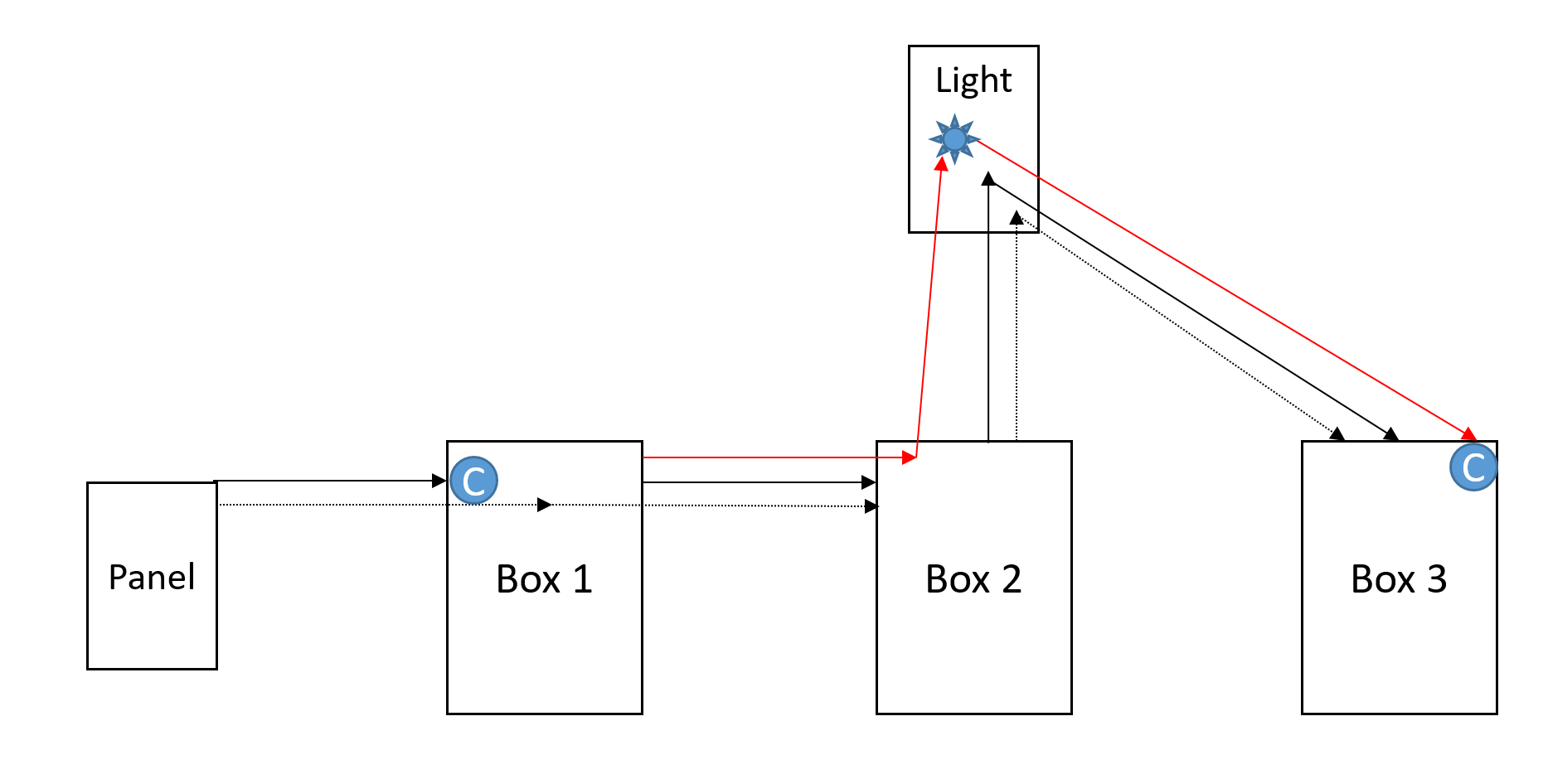
I don’t know if @Bry 's diagram has it exactly correct. I doubt that there is a red to black junction anywhere in the wiring and there is probably a bunch of 3 conductor bundles between the various boxes in this circuit. I think it looks more like this:
What will happen in this scenario is you will have white wires that are hot in boxes 2 & 3 in some scenarios (probably not to code). I think that you’re in no-man’s land if you’re expecting to use aux switches. I have a setup something like this in my kitchen and I think you might be able to avoid cracking open the light box if you’re willing to switch to all Inovelli switches and use something like Hubitat’s Mirror Me App. Wiring would look something like this:
Yep, you’re not really going to know until you get to the ceiling box to inspect.
I agree it’s less likely that there are conductors of two colors bundled as @shawnballs pointed out. It makes it more confusing when the boxes are provisioned. On the other hand, keeping the color bundles consistent introduces a switched neutral, which at least presently is not allowed by code in most places. But it really depends upon where you are located and what code you were subject to when these legs were run. Since all of @budmannxx’s multi-ways seem to be like this, I’d guess that this wiring goes back to when the house was built.
Can’t wait to see how this shakes out . . .
EDIT: While you’re up there looking around, you are also going to want to note if the light is between boxes 1 and 2 or boxes 2 and 3.
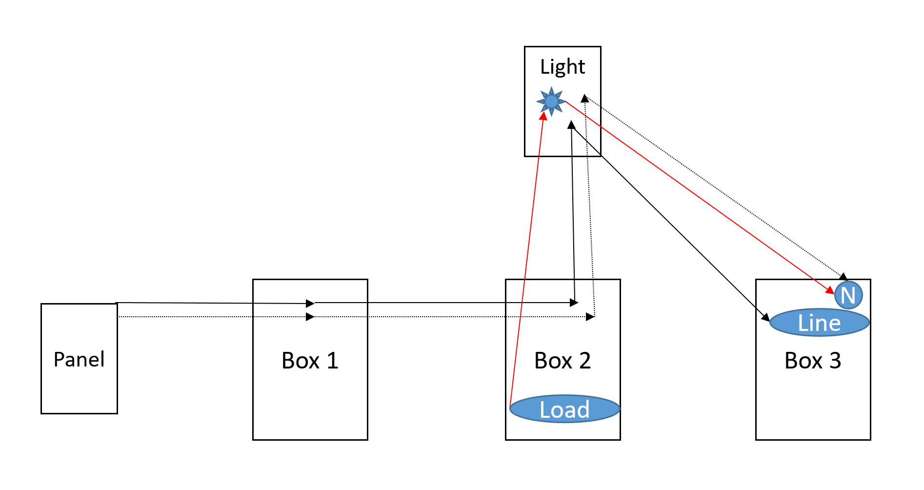
Here’s my most likely map. Sorry no pretty picture.
Looks like wire 1 in the light goes to box 1, and wire 2 to box 2.
Wire 1 is carrying travelers (red/black) and neutral from switch 1 to the light.
Wire 2 is carrying travelers (white/black) and switched hot (red) to box 2.
The cable from box 2 to box 3 is carrying travelers (white/black) and switched hot (red). That is exactly what I’d expect to be in a 3 wire cable that is the only cable going into a box with a 3 way switch at the end of a run.
I think you can do this with the inovelli switch in box 1 and aux switches in the other two boxes. Inovelli in box 3 is definitely impossible, unless you’re using associations and multiple inovelli switches. Inovelli in box 2 and aux switches in 1 and 3 I think would only work if the light was wired in between boxes 2 and 3, not 1 and 2.
In box 1, wire line and neutral to the inovelli switch the obvious way. The 3-wire cable to the light should connect to the traveler (red), neutral (white) and load (black) terminals on the inovelli switch.
In the light, connect W3 , W1, W2 and fixture white (neutral). Connect B3, B1 and fixture black (switched hot). Connect R1 to R2. Leave B2 unused.
In box 2, connect both whites to neutral on the aux switch, both reds to traveler. Leave both blacks unused.
In box 3, white to neutral on aux switch, red to traveler, black unused.
You could probably also do this with dumb switches in boxes 2 and 3, but I’m not sure how to wire that
Actually, I think you can do this without changing any wires in the light, box2, or box 3, using dumb switches.
Wait for someone else to confirm whether they think this will work before you try it.
You’d wire the inovelli switch in box 1 the same way as with the aux switch solution I posted above. Wires in all other boxes would be the same. This is electrically equivalent to the “load in both boxes” dumb 3 way configuration from the instructions, but with a 4 way followed by a 3 way, instead of the dumb 3 way