Hey @JohnRob and @Bry do I have quite the pickle that I’m hoping you guys can help me out with. Wanted to post it to the community in case anyone else runs into this issue (and to show that I’m human too and run into issues with my own smart home lol).
So, here’s the scenario and I’m starting to think it’s something with my actual wiring, which I’m afraid of.
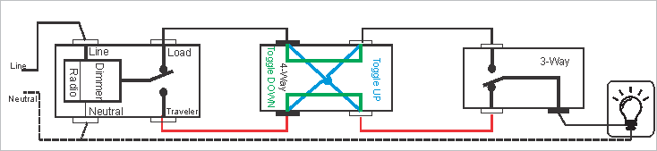
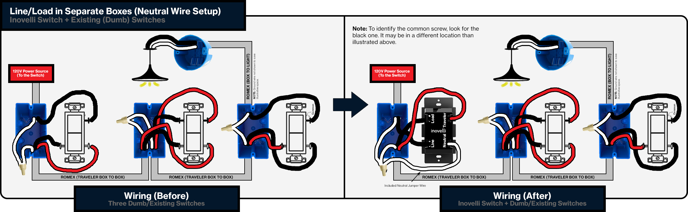
I had a GE switch (smart switch) installed in a 4-Way setup using aux switches (99% sure it’s Line/Load in separate boxes) such as this:
About 10 months ago, I replaced it with our new Gen 2 On/Off switch and it worked perfectly up until maybe a month or so ago when I thought it just died (almost wrote a ticket into Inovelli support lol jk).
I replaced it with a different Inovelli switch and the new switch would not power up at all. Great, I’m thinking… Then I tried it with a confirmed switch and same thing, nothing lit up at all. I even tested the original switch and the 2nd one in a different area and they worked.
Ok, so flash forward to tonight. I take another switch, test it in a 4-Way at work and it works perfectly. I take it to my house and again, nothing powers on.
So, I rip out all the switches and replaced the fixture (just in case) wired all the blacks to blacks, neutrals to neutrals, and capped off the travelers to have always power to see if the light would light up. The light does not light up at all… what does this mean? I used a dry contact meter and it lit up.
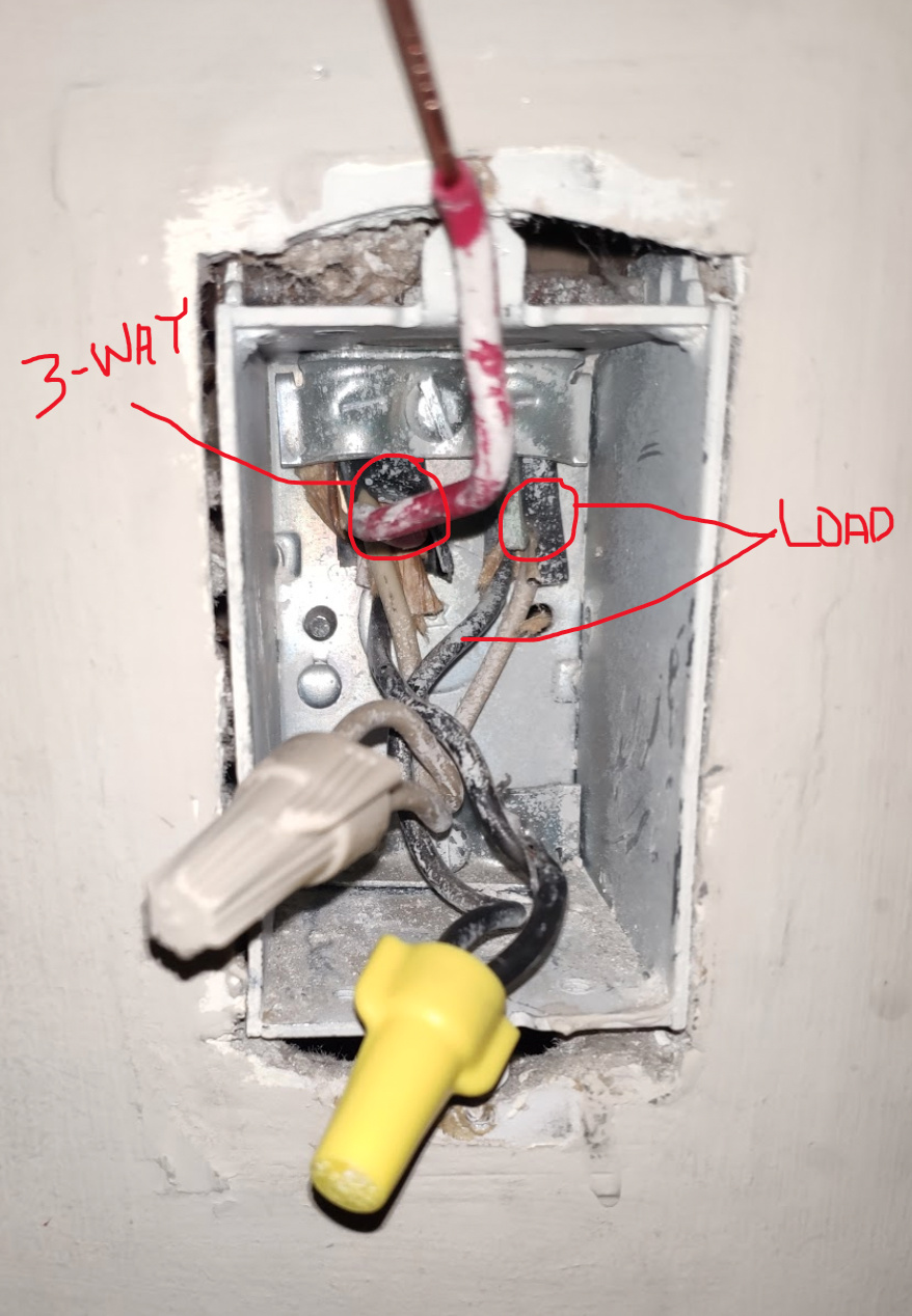
Switch #1:
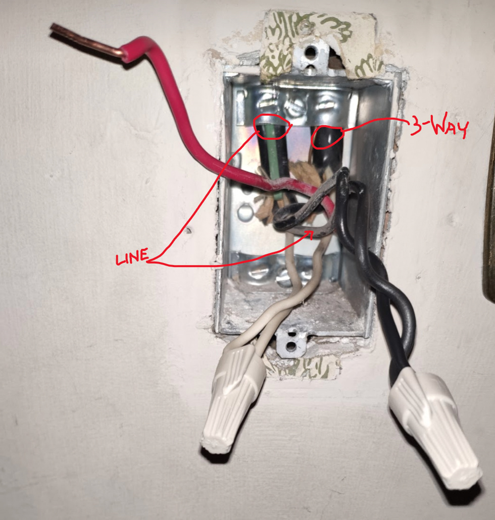
I’ve verified this is where the line is by detaching all the wires across all three switches and dry contacting the black wires and this was the only one that was hot.
Switch #2:
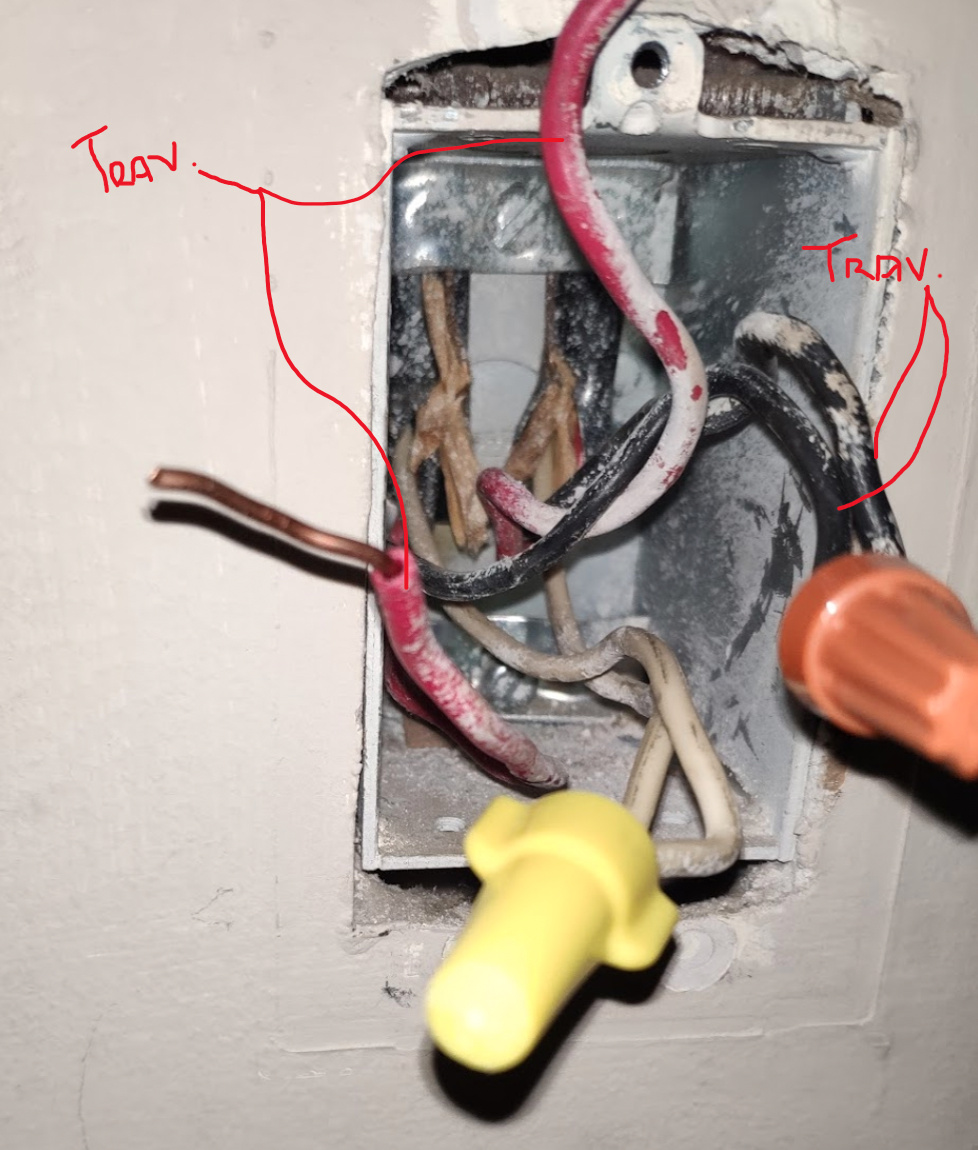
Switch #3:
Next step is to get the multi-meter from work, but I also put the dry contact meter up to the fixture and it lit up. I’m just honestly not sure what it could be as it seems there is some sort of power at the switch as the meter lights up every time, but the smart switch does not turn on, nor does the light/load turn on.
I’m stumped