Recently I’ve decided to change all switches in my house from toggle to rocker switches, and as part of that install a few smart switches at key locations. In my case I’m using the LZW30-SN switches (I believe with neutral installation).
Please bear with me as this is the first time I’m taking on such a task and do not have much experience with wiring. I can share with you that I’ve already replaced multiple switches around the house, both single pole and 3-way, successfully. In fact, I’ve successfully installed one of the LZW30-SN as a 3-way switch, and both it and the dumb switch seem to operate correctly (including remote control). I’m using Hubitat as the hub.
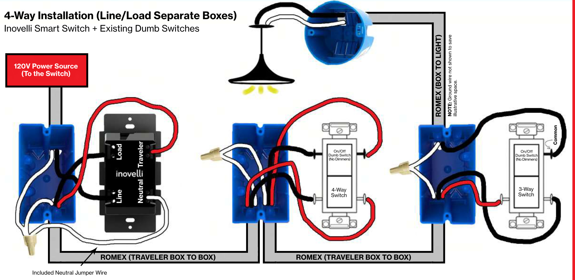
The challenge I experience is with a 4-way switch installation. The 2 other are dumb switches. As far as I can tell, the smart switch is at the beginning of the line. The wiring of this switch looks pretty much identical with the working smart 3-way switch installed right next to it.
The working switch is to the right, and the one giving me trouble is the middle one.
I’m not entirely sure this is a wiring issue, could be configuration. What I experience is the lights not turning on, no matter which switch is being used (smart or dumb ones). However, when I flip any of the switches, I can see the LED indicator alternate between on/off. I’ve tried replacing the smart switch with a dumb 3-pole switches and the lights work fine, so I’m a bit unsure what might be the reason.
Any help would be appreciated. I can also provide additional pictures as needed.
Since you seem to be unsure of your wiring, lets start there and check that first. We need to identify the function of the two 3-way switches in your circuit.
In one typical 4-way wiring scheme, power is supplied to one 3-way switch, routed through a 4-way switch and then routed to another 3-way switch and then to the light. We need to figure out if that’s what you have.
We’ll take this from the position that the dumb switches are working correctly.
Pull out your two correctly wired 3-way switches. They’ll have 3 terminals on them. If you have the schema I described above, there will be one 2-wire and one 3-wire partially wired to each. We need to focus on the 2-wire Romex. One of them will be the incoming power and the other will be going to the light.
Remove the black conductor from each of the 2-wire Romex connected to the switch. Use a volt meter to test between each of them and the probably white neutral bundle in the box. You are looking for a CONSTANT 120V. Just to be complete, once you’ve identified that conductor, test with the other switches in various positions to insure the 120V is constant. The box with the constant hot will be where the Inovelli will go.
Report back with a description once you’ve found it. We’ll call it left or right, as the 4-way switch will be in the middle.
Note: There are other wiring schemes, so if you’re seeing something different, let us know.
Perhaps I wasn’t clear in my description, so let me make sure. The two dumb switches I have are one being the 4-way switch and one being the 3-way switch. I’m guessing the dumb 3-way switch goes to the light and the smart switch is connected to the power. This could be wrong, I’m just basing it on the fact that it’s right next to the other 3-way smart switch that is working correctly.
Unfortunately, I don’t currently have a volt meter, only a non-touch voltage tester. If the volt meter is necessary, I can have one tomorrow to do further evaluation.
Ok, let’s go back even farther. How many switches control this light? If you have a four way, it’s at least three.
We are starting with the complete dumb switch configuration. We’re not talking about smart switches yet. So you do your diagnosis with all dumb switches installed and working. Since you’re guessing, we are starting at the beginning.
@Bry Will do the testing tomorrow and report back. There are 3 switches overall. I’m aware that the middle one is the 4-way one, and the two at the ends are 3-way.
I’ve removed all 3 switches, and tested the wires with the voltmeter (looking for that steady 120v) I’ve identified the first switch in the series, and connected the live one to the Line, the traveler to the Traveler and its buddy to the Load (Neutral and ground are connected as well) - all to the Inovelli smart switch.
Then I moved to the next switch, tested the wires again, and since that’s a 4-way switch, I’ve identified the live wire, and connected it and its corresponding traveler to the in, and the second wire set to the out.
In the final switch, even though it’s obvious that the couple of wires are the live and traveler, I’ve verified that it’s indeed the live wire, and connected the wires to their corresponding points in the switch.
With all the testing, the lights still do not turn on.
As a next step, I’m considering replacing the smart switch with another smart switch that I know is working, to check if the problem is with the switch itself.
If you have any other thoughts or suggestions, I’d appreciate it.
Okay, it looks like it’s the switch itself. With the other smart switch installed instead, I can turn the lights on and off, though it doesn’t coordinate very well with the other dumb switches (but at least in some configuration of on/off the lights do turn on). Trying the faulty smart switch where the working one was, the lights do not turn on no matter what.
I’ll see if I can get a replacement for the faulty switch.
Any suggestions how to fix the operation of the functional switch in the 4-way config?
It’s an on/off switch. However, only resource I found to update the firmware is Knowledge Base Redirect – Inovelli and that’s a no go for me as I don’t have a windows machine.
@harjms It’s a Black Switch, LZW30-SN, at least according to the first post.
As @harjms stated, it could be the switch’s programming, but it could also be your wiring.
Let’s confirm the wiring. From what you have described, you have the incoming hot (line) in the first box and the load to the light in the last box. It should look like this:
So just to confirm in the left box, you found a hot in the left box, probably coming in on a 2-wire Romex. The black from that Romex goes to the Line on the Inovelli. The white neutral from the same 2-wire gets pigtailed and connected to the Neutral on the Inovelli.
Still in the left box, you have a 3-wire Romex that goes to the 4-way switch. For that, the white goes to the neutral bundle, and the red and black are connected to the Load and Traveler terminals on the Inovelli.
In the middle box is the 4-way switch. There are two 3-wire Romex in this box. You identified the three wire coming from the first box. The red and black go to one pair of terminals on the 4-way switch, same color terminals, usually either the top or bottom set. The red and black from the other 3-wire which is going to the last (right) switch go to the other two terminals on the 4-way. Both whites get wire-nutted together.
In the last (right) box, you have 3-wire and a 2-wire Romex. The 3-wire is coming from the 4-way switch, the 2-wire is going to the light. The red and black from the 3-wire goes to the two brass terminals on the switch. The black from the 2-wire goes to the black terminal on the switch. The two whites are wire nutted together.
Go through your connections and confirm. If they look good, we can start testing with a meter with the switches in place to see where it is failing.