I’m trying to replace a 4-way switch with a Red Series On/Off and use the remaining (2) 3-ways as dumb switches. I included what my circuit looks like. The 4 way switch appears to be first in line and looks to only have travelers on it (2 red wires and 2 white) then the 3 ways are both dead ended. The 4-way is in a box with 2 other switches, one of which is controlled by another breaker. The main hot line comes into the box and is wire nutted (feeding the other switch on same breaker) and goes back out. There is a 2nd set of black wires nutted together with what I can assume is the load lines to/from the 3 ways. I am at a complete loss as to where to start to make this work? Is there a way to make this work and still use the remaining dumb switches? Or do I need to switch them all over to smart switches and group them together?
So if for both of your 3-ways you only have all three conductors from the SAME 3-wire Romex connected to them, then there are two possibilities.
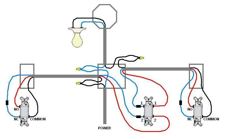
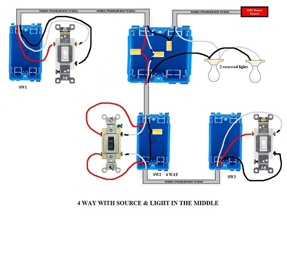
1 - Power is being fed to the light first and then down to the 4-way switch. This will be a non-neutral at the switch box.
2 - Power is being fed to the 4-way switch box. This will be a neutral at the switch box.
The way you can differentiate these is by the number of 2-wire Romex “involved” at the 4-way switch box, related to this switch leg. By “involved” I mean either connected to the switch or routed to the other switches. Look at the 2 drawings below.
In the power to the switch box, there are two 2-wire Romex involved. There is one for the incoming power and one for the light. In the power to the light, there is only one 2-wire involved, the one to the light.
You are going to have to figure out which of these you have. I followed most of what you explained, but can’t quite determine if the power is being fed here for your 4-way or for the other switch leg you referenced.
Once you know which of these you have will dictate how it’s wired. I’m pretty sure you are going to have to use Aux switches. Certainly if you have a non-neutral power to the light, and probably if power is being fed to the box.
I have power to the switch box based on the diagram you showed. There is neutral available in the box as well.
I thought about putting the red series switch in another switch location and using aux. switches but since the lines dead end I don’t have a load wire since there’s only 3 wires/1 romex at the other two locations. Unless of coarse I don’t need one?
My first choice is using the red switch in place of the 4 way since it’ll be part of a bigger 5 switch panel so it’d be nice if they all matched lol.
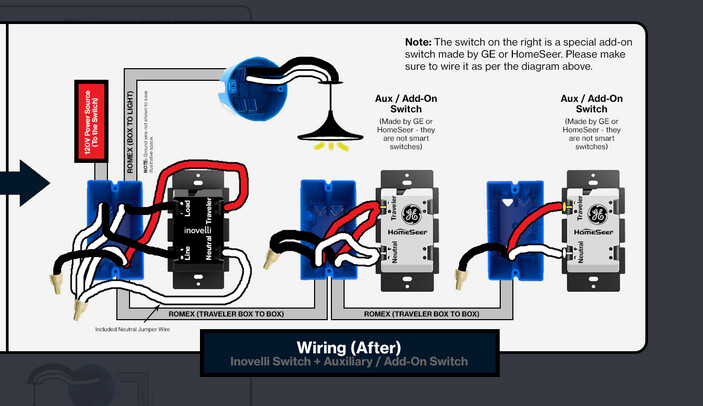
Putting the Red Switch in place of the 4-way is your easiest option, since you have both the line and load there. So you can use this drawing, the only difference is that you’ll have one Aux on each side of the Inovelli. Wire the Inovelli as shown (it’s really just a 2-way wiring config) and then send a Traveler and a Neutral to each of the Auxs.
Ok just to confirm I’m thinking about this the right way. I can just put both of the neutral lines and both of the travelers from the old 4-way on the neutral and traveler legs of the inovelli switch since it’s first in line and both aux switches will need them. Then run the line and load wires to their respective legs on the inovelli?
Yes. I’d use the red conductors on the 3-wires to run to the Traveler terminals. You can use the two holes on the Inovelli for that. For the neutral, you will have to pigtail to the Inovelli. Then you can use the other hole for one neutral/white on the 3-wire and put the other neutral/white on the neutral bundle.
Wire nut the single black conductors to keep them from touching anything.