Installed my first 3 Inovelli Switches with no issues… Being over confident, I decided to try on a 4 way switch I have and I got stuck and learned some fun things about my house.
I either had a drunk or genius electrician wire my 15 yr old home. Here’s what I found:
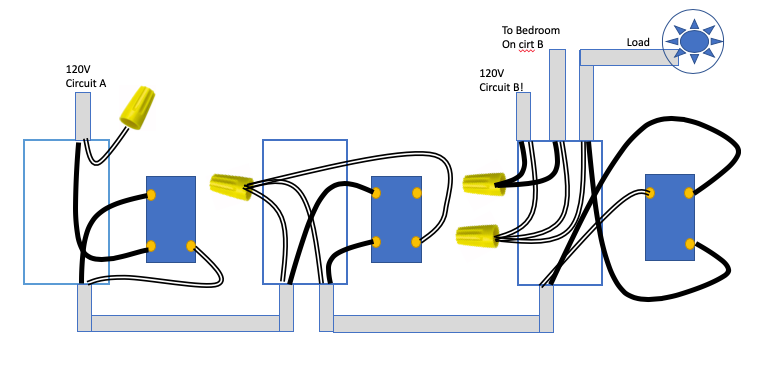
Electrician set up a 4 way switch system using only 14/2 romex. I was expecting 3 wire Romex… How does this even work? HTF
After getting my ass shocked, I realized the electrician cross connected neutrals across 2 different circuits. WTF
See the drawing… I have no idea why this works… I obviously want to isolate the 2 circuits…
Questions:
Any thoughts on how to wire this so all 3 switches control the load?
I was hoping to use a single Black Series On/Off in the chain but I can’t see how that will work now since there are no traveler wires
In Insteon world, 3 ways are created by master/ slaving switches to create a virtual 3/4 way switch. Not sure if this is an option but willing to do this if this is the only way. Is this possible in a Zwave world?
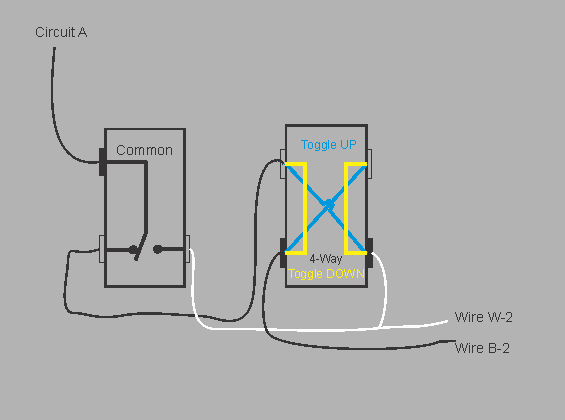
I changed the wiring on the far left switch slightly. For the far left 3-way to work, the Circuit A black wire must connect to the “common” (sometimes a black screw) terminal on the far left 3-Way. Please check this assumption is correct. Perhaps a photo might help.
Its not clear how the 4-way could function as intended. If the far left 3-way is switched so the power comes out the white wire, the 4-way has no capability of interrupting power as it is connected right through to the far right 3-Way.
Do all three switches function to turn the load on and off for each combination? From what I see they shouldn’t. Please check.
I either had a drunk or genius electrician wire my 15 yr old home
Let me say it this way… he** wasn’t a genius. In fact if he were licensed you could have their work inspected and require him to redo it with 3 wire Cable. The current wiring does not meet the NEC requirements (NEC = National Electrical Code). Specifically he is using the hot (line) wire from one circuit and a neutral from another circuit which violates code.
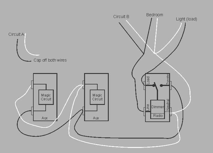
To make it work and meet code, if the load is a light, you can put a Red dimmer in the far right location and use two Aux switched in place of the 4-way and far left 3-way.
If this works for you, I can suggest specific wiring.
First of all, make sure that he didn’t use two 2-wire Romexs instead of one 3-wire. While not exactly conventional, I’ve seen it done and it wouldn’t violate code.
Regarding two circuits on one neutral, that may not violate code. It’s typically done to run two circuits over a 3-wire Romex. This using a shared neutral works so long at the breakers are adjacent to each other in the box. What happens is that you are using both legs of the 220, so the two circuits are 180 out of phase and don’t overload the neutral. If the two breakers aren’t on different legs of the 220, that’s another matter.
I think you misunderstood my statement. I specifically stated " using the HOT from Circuit A and the NEUTRAL from Circuit B is specifically forbidden by NEC Code.
Thanks for the reply… I just had my breaker box redone… I didnt save the circuit layout before but the 2 circuits are definitely NOT on the same leg anymore!
I was hoping the same thing – that the electrician used 2 -2wire romex as well… There were just so many wires jammed into that 3rd box… It made sense. When I got shocked, I realized something was amiss and painstakingly traced out every wire in those 3 boxes.
An AUX switch is like a companion switch that offers ON/OFF and Dimming functions by communicating directly with the main dimmer. They are NOT 3-Way “dumb” switches. Their benefit is they only need two wires.
Inovelli states that both HomeSeer and GE’s aux switches will work with the Red series dimmers.
I’ve not seen it done, however the LZW30_Manual shows an aux switch with an ON/OFF device, perhaps @anon64478871 can verify if this is indeed the case.
I’ve drawn the white wire going to the top connection of the Aux dimmer. In reality there is no polarity with the Aux dimmers they can be wired either way.
I understand Aux term now… I’m moving from Insteon and to Zwave and learning the lingo… I guess I need to go do research but how do the Aux’s tell the master what to do? Just wiring up the Black to the traveler tells is what to do? No slave/listener programming required? If so , this gets better and better.
@JohnRob Thanks for all your help. I found another 3 way switch in my house that has this same pattern with Neutrals from 2 circuits… It wasn’t an accident what my electrician did.he was just saving money on romex… <sigh…>
Question on the wiring using the Aux controllers. Do the Auxs always have to be downstream from the power source and the load?
I can do what you drew but I would prefer to have these lights powered from Circuit A… I assume the Smart switch needs to be where the Load is… Is there a way to put the Auxes in the left and middle and use the power from circuit A?
Unfortunately No. Without a 3rd wire (or sharing a neutral) there is not enough wires to get power and control out of the left hand box.
Even if the Red was in the left hand box it still would not work.
I don’t know your relationship with the electrician but from what I can see they should not have a license.
You might want to consider capping off the wires in your AUX switches and get some wireless switches to make up for the loss of physical switches.
Also since all neutral wires run back to the grounding bar in the breaker box, I don’t think you are in any danger. In the first image I can only see a single line wire powering this.
As a former electrician, perhaps you could comment on the image in the first post. There were comments on this probably using 2 hot leads in the mix. I only saw one.
I can only help using our pre-defined diagrams for liability reasons. I can’t help as a employee for anything else. This is why we have a community forum so that other users who have run into same issues might share what they have done.
God forbid someone here attempts to help and the end user gets electrocuted or they cross a wire and the switch blows… This is why I can’t offer any help beyond the scope we already provide.
First of all - I love the Inovelli community… I spent the last few days changing out 3 different 3 way switches. All 3 places used the same pattern of using the hot lead from one circuit at the beginning of the chain and the neutral from a different circuit at the box where the load wire is…
Easy to fix now I know what I’m looking…
I don’t even understand how this pattern works and yet it works… I have corrected all of these.
Im currently using some GE addon switches. Is it possible to use a nice looking Inovelli Switch for the addon switch?