Also having a 3-way issue

@CLesto - One thing you may be able to help determine is if the load is looped around the incoming line. See


You can see the loops around the line. The black coil goes to my 3-way switch (load). On the other side, the dumb 3-way has a similar coil…Granted not all electricians = same. It just may help follow the lines.

Otherwise, you could remove the light fixture and see what type of connections you have inside the light gang box.

@harjms I wish it would be that easy. So one thing I expected to see and one thing I didn’t expect to see. I saw one bundle of wires tied together, which were all neutral. I completely expected to see that. What I didn’t expect to see were a bunch of black wires all tied together. I’m guessing those were all ties off of line/common. I’d have to take a closer look at it as I was pushed for time. But the wires going to the three way switch were black, white and red. Red was obvious, the black I THOUGHT was the line, but now I’m thinking it wasn’t. I’m starting to think that was the load and the white was Line/common. Anyways I’ll have to take a closer look and if I’m still confused I’ll take a pic.

Here’s the pic. The switch to the far right is the three way that controls light I’m trying to replace.

Hopefully it makes sense to someone, because it doesn’t make any sense to me.

Just looking at this quickly, here are my thoughts (not an electrician either, nor do I play one on TV).

The bundle of white is the neutrals all tied together. The bundle of black is the line (coming from panel) split out to your switches and or loads. This is common and mostly all my gangs are like this (bundled and just uses feeders). The first switch is using a hot from the bundle. Your second switch is using a hot from the bundle. Your switch you’re referring to (3rd switch) is not using this bundle of black as line. The hot from the bundle is actually going into the 14-3 that is connecting to your 3-way switch. I imagine it’s going to the light where it ties to your other switch or the load. The 14-2 (blk wire tied to your 3-way switch) looks like the common (load), but it doesn’t make sense to me. I’d have to look at the connection in the middle to help determine it. With that being said, It does look like they’re using the WHT/RED as a traveler pair. Got a pic of the other switch?

I don’t pretend I’m an electrician either. Honestly AC gives me the willies when it’s not horribly obvious what’s going on. I pretty much had a feeling about the line bundle. But when I saw the 3 way didn’t tie into that I was really confused.

I’ll see if I can get a pic of the other switch as well as the connections at the light tomorrow.

AC isn’t too bad. Just got to ‘respect’ it. I do “some” power at work, but it’s 440 VAC, 3-PH…so it’s a little bit different. Much easier when it’s PH A, B, or C to GND.

I think your switch (not pictured) should be the place where the Inovelli switch is installed. With pictures of the other switch, we can probably work it out. I’m still having issues with my 3-way working, so I’m hoping @Eric_Inovelli and @EricM_Inovelli can figure it out. I’m going to attempt to install another 3-way in the basement tomorrow to see if I’m running into the same issue.

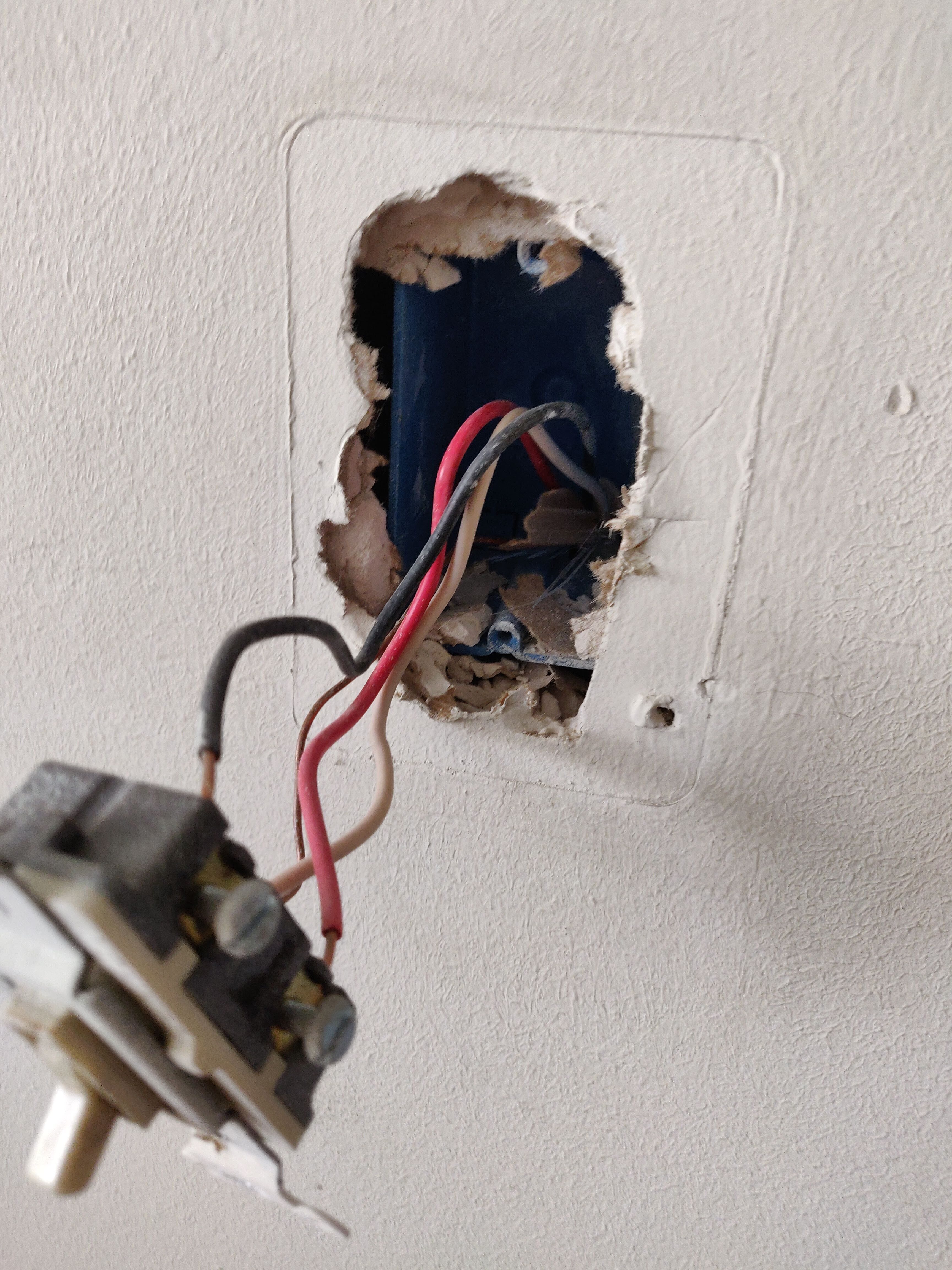
Sadly I don’t think I’ll be able to put the switch in the opposite end of the circuit. Doesn’t look like there’s a neutral there.

Mind is blown. The BLK looks like it’s coming from the LINE bundle, BUT there may be a wire change where the light fixture is installed. Best thing I can recommend is get a Klein electrical pen or use a multimeter and trace it out.

@harjms @Eric_Inovelli So after scouring the webs looking for 3 way wiring diagrams, I have a feeling my wiring (at least for the most recent 3 way I’m showing) is more like the below. I’m REALLY starting to hate the wiring in this house.

Tagging @EricM_Inovelli as well!

@CLesto - That one is a bit harder…I was almost going to say the far end, but then again, there’s not neutral available. You may have to use an Aux Switch on that circuit. Let me look at it some more and see if there’s something I can think of…

@CLesto If that is your wiring circuit then this diagram should work for you.

Notice that the load wire (black) is coming from box 2, connected via wire nut at box 1, and then goes up to the fixture.

3 Likes

Thanks! I’ll give it a try tomorrow. I’m not sure if I feel motivated enough to give it a try after 10pm :laughing:

@EricM_Inovelli came in for the win. You can use a wire nuts from the PKG to hook up the neutral to the switch if you wanted instead of wiring both neutrals through the switch.

@EricM_Inovelli That worked!!! So ONE of my two 3-way switches are working. Now if I can get that last one working I’ll be golden!

Thank you so much!!

1 Like

@EricM_Inovelli, @Eric_Inovelli I’m starting to believe the first 3-way I mentioned in here is probably not wired the way I thought it was. Here’s pictures of the wiring. Unfortunately getting pictures at the lights are going to be extremely difficult.

This is the switch where power source comes in from the box. Or at least I’m assuming that.

Unfortunately I’m limited to one image per post. See the next posts.

This is the other switch.

I’m guessing there IS a possibility my wiring could be like this

Sadly I won’t know unless I can either get into my attic or drop the light. Either way it’s about 10 feet up and over a stairway.

I may wind up having to bring in an electrician to take a look. If I did, what should I mention to them in order to rewire it for a Z-Wave switch?

@EricM_Inovelli I’m in the same boat … almost (as the 2 traveler wires for the remote switch/box 2 are reversed). I’m wondering on the “should work” context above the diagram. Was this something you tested and got it working because I can definitely rewire/flip mine to match it.

edit: the diagram does match the one on page 6 of the instruction that came with the red series… so it probably not a one-off solution.

1 Like

Dang, that is a fun wiring schematic. :slight_smile:

Of course I encourage you to consult an electrician but some general words of advice:

Looking at it the idea is the same as the one I posted earlier. The main differences is that the Line is being fed from the lights and going into the common screw. So that would need to go into the line for the Inovelli. The red & white wire would go to the load and traveler, and the common from switch 2 would come back to the switch 1 location and back up to the lights (wire nut at switch 1 location).

I haven’t tested this diagram exactly, but have tested similar.

If your wiring is like this diagram, you likely don’t have a neutral If you trace white wire from the source, it doesn’t go directly to the switch (it goes through a bulb first). This means when the light is turned off the switch itself also loses power.