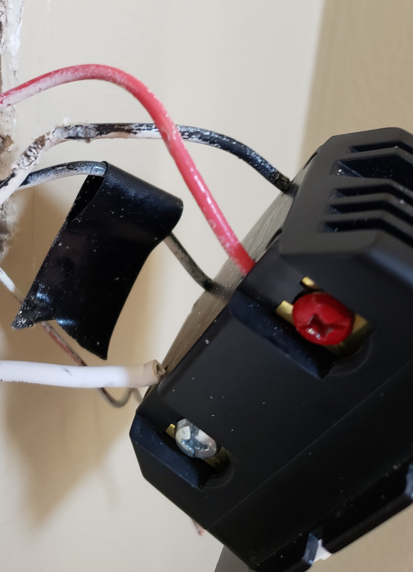
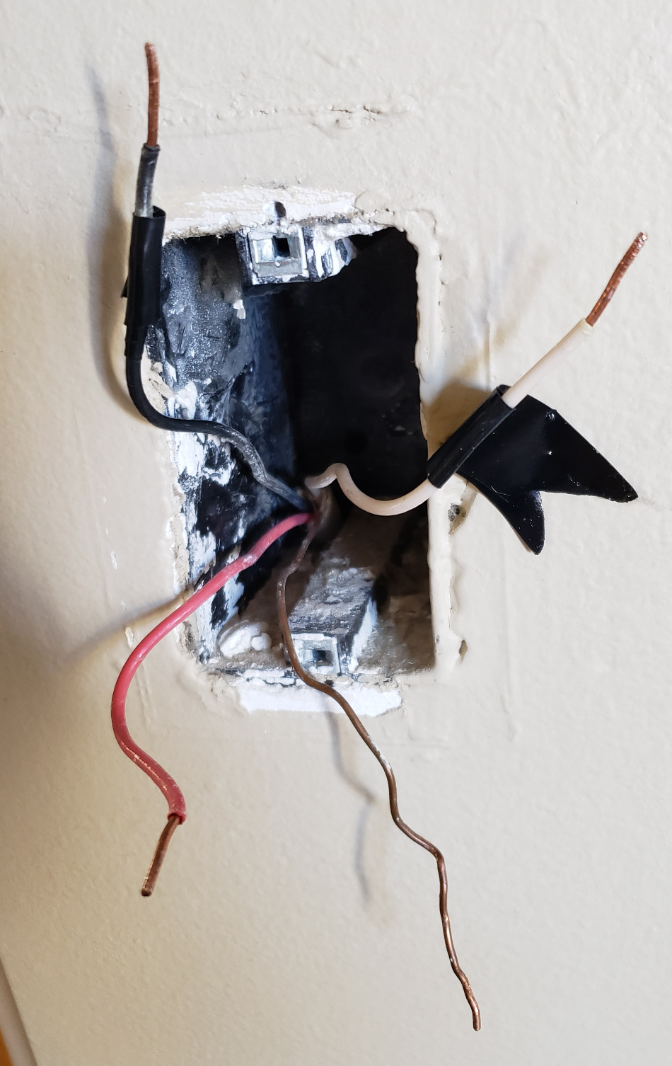
I have a 3-way setup, prior working with dumb switches. I’ll identify the two as “Box A and B”, “A” which has neutral for the smart switch, and “Box B” which I thought would be the dumb switch.
I have a couple of problems. One is that “Line” for Box A is not hot unless Box B is switched on. The tape black wire in Box A doesn’t go hot unless Box B is on.
The other is that the red traveler wire in Box B is always hot, even if Box A is fully disconnected.
What’s happening in my setup is that the Red in Box A won’t turn on at all, not even the dim LED, unless the dumb switch in Box B is on.
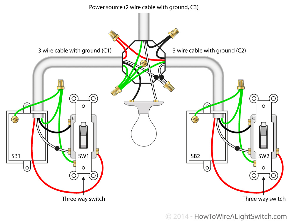
I can’t help with the switch wiring, but I can help with the wiring configuration. Because you only have one three-wire in each switch box, that suggests that you have power to the light with the light in between the two switches. Normally, one box would have a constant black hot (which would be the “Line”) but in your case it seems to be the red instead.
I would pull the light and look at the wiring there. You should find a two-wire where the black is always hot, and two three-wires going to the lights if I’m correct.
The reason you think that what you think is your “Line” not hot all the time is because that’s not the “Line”. It’s one of the travelers being energized only when the other switch is in one position only. More than likely, the “Line” is the constantly hot red in Box B.
That makes sense. Unfortunately, I won’t be able to get behind the lights to check since they are vaulted. I don’t have a neutral in Box B, Is there a wiring guide for using the Red in this setup? I’ve been trying to keep the Red in Box A since it has neutral. Do I need to try to move the Red to Box B?
Right now, if your wiring is as in the graphic I posted, you don’t have a neutral in either box. The neutral stays at the light and the white conductor is used as a traveler.
I’m not knowledgeable about Inovelli’s three-way switch wiring, so I can’t comment on how to wire it. However, one thing to explore is whether or not the Inovelli needs two travelers. @eric_inovelli or someone from Inovelli should be able to weigh in on this. The reason I mention this is if you don’t need both travelers, then you can re-wire to make one of the current travelers a neutral so that you route a neutral to one of the switch boxes.
That’s a really interesting idea! I didn’t consider that I could get neutral to “Box B”. Definitely would appreciate any input from Inovelli on this. Thanks!
Am I crazy? Is the white wire in both the OP’s photos not the neutral wire?
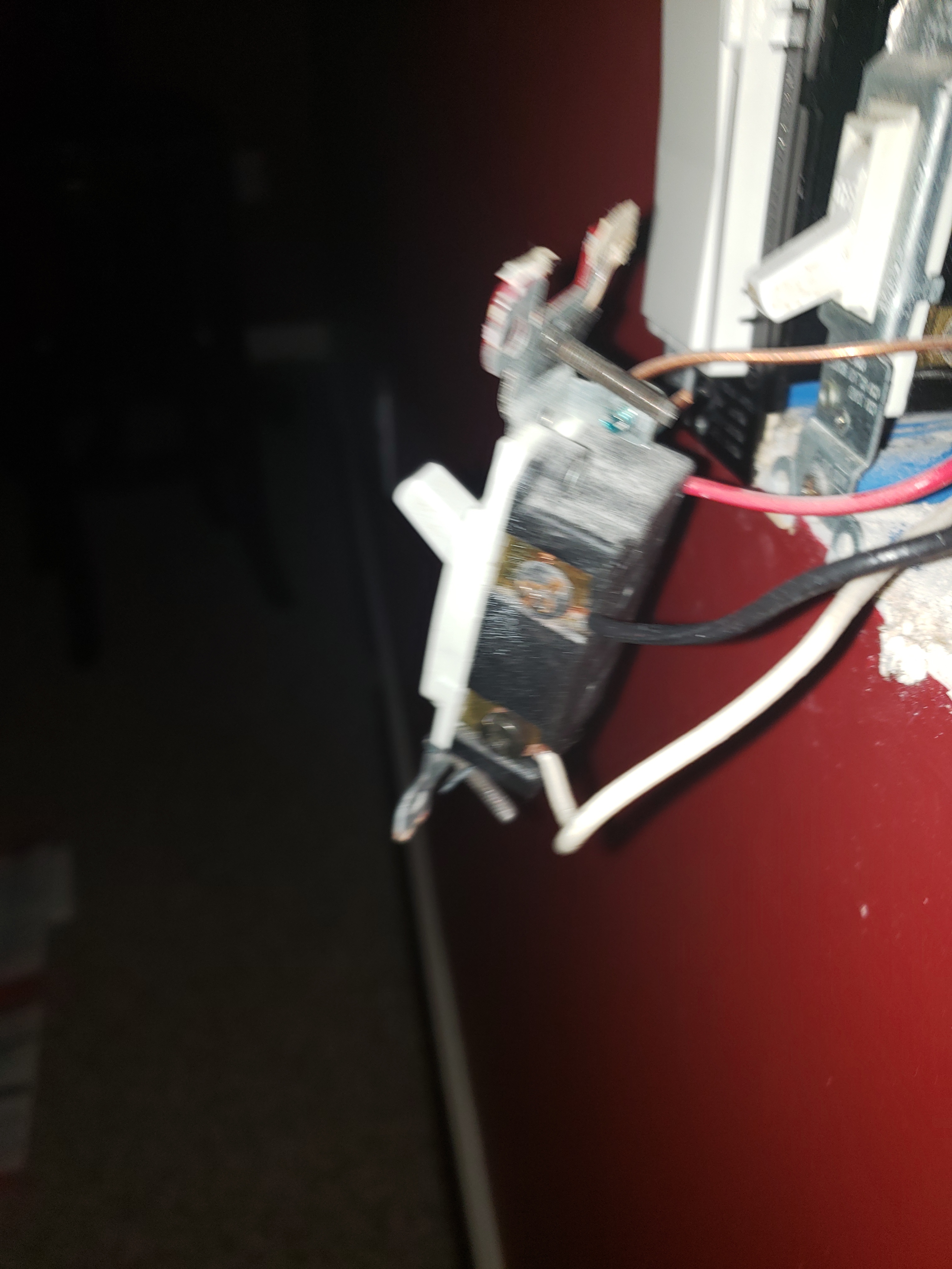
OP, I have a similar looking setup, which I just got working today. Something odd I had to do was go in through the on-switch config to turn neutral to on(up) and 3way to dumb (up). Then after wiring the dumb switchas so (photo attached), it finally started working
If White in Box B is neutral, and Red there is always hot, then that leaves the black wire only, which would make it what? traveler or the load?
I’m just guessing but it seems I have more what Bry says where the light is between the boxes, and unfortunately, Line and neutral aren’t in the same box.
I’m sure you’re not crazy as some of these three-way wiring configurations can get confusing.
Here is why neither of the two boxes in the diagram I posted have a neutral. I can’t say for sure if yours or the OP’s match the diagram, but if they do, here is the explanation:
The power is fed to the light via a 2-wire. The white neutral is connected to the light. The black hot is connected to the black 3-wire going to SW2 on the right. So depending on SW2’s position, the hot is then routed over either the white or red of the 3-wire. (Notice the black dot on the white wire. You’ll sometimes see an equivalent black tape on a white Romex. It tells you that even though the wire is white, it can be hot.)
So now we have power being routed back to the light box via either the white (black dots again) or red 3-wire from SW2. In the light box, those two wires are connected the the white and red 3-wire from SW1. So now power is being routed over either the red or white to SW1. So this is why the white in SW1 is NOT a neutral.
So just finishing this up, now that power is at SW1 on either the white or red (depending on SW2’s position), power will be routed back to the light via the black 3-wire connected to SW1. You’ll see that the other end of that black is connected to the other terminal of the light.
In your Box B, it’s the Red that is always hot, correct? I am guessing that the red wire in Box B was connected to the black screw on the old switch, correct? If those two are correct, then reinstall the old switch in Box B wired exactly as it was previously.
Now go to Box A. Using a proximity tester, you’ll find that one of the two wires that were previously connected to the gold screws on the old switch is hot, probably the white or the red. Move Switch B to the other position and go back to Box A. Using a proximity tester, you should find that the other wire previously connected to the gold screws is now hot.
The third wire, if your setup matches my diagram, routes power back to the light. So since you know that at one point or the other the remaining two wires in Box A can be hot, there is no neutral there.
Again, this is all based on my diagram. If you don’t have this configuration, then this won’t apply.