I’m working to install a blue series 2n1 in a 4 way but I’m struggling to figure out how it will get added in. It’s a 4 way with Neutral and line/load in the same box but the diagrams I’ve found have the four way switch itself in another box (i.e. line/load/switch > 4way switch > switch) and with mine the four way switch is in the box with the line/load (i.e. switch > 4 way switch, line, load < swtich). Not sure if it matters but the other two switches only have the three wire in them and there is no other wiring for the circuit in the box.
As far as I can tell I don’t think I can install the smart switch in place of the four way but also I don’t think I can install it on either end without having additional wiring.
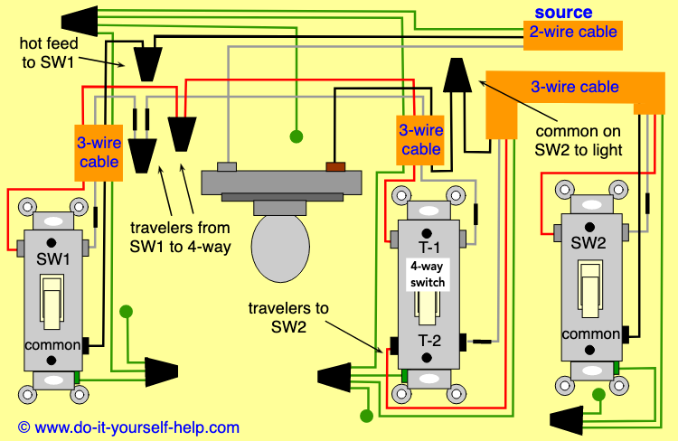
From what I can tell this diagram matches my setup
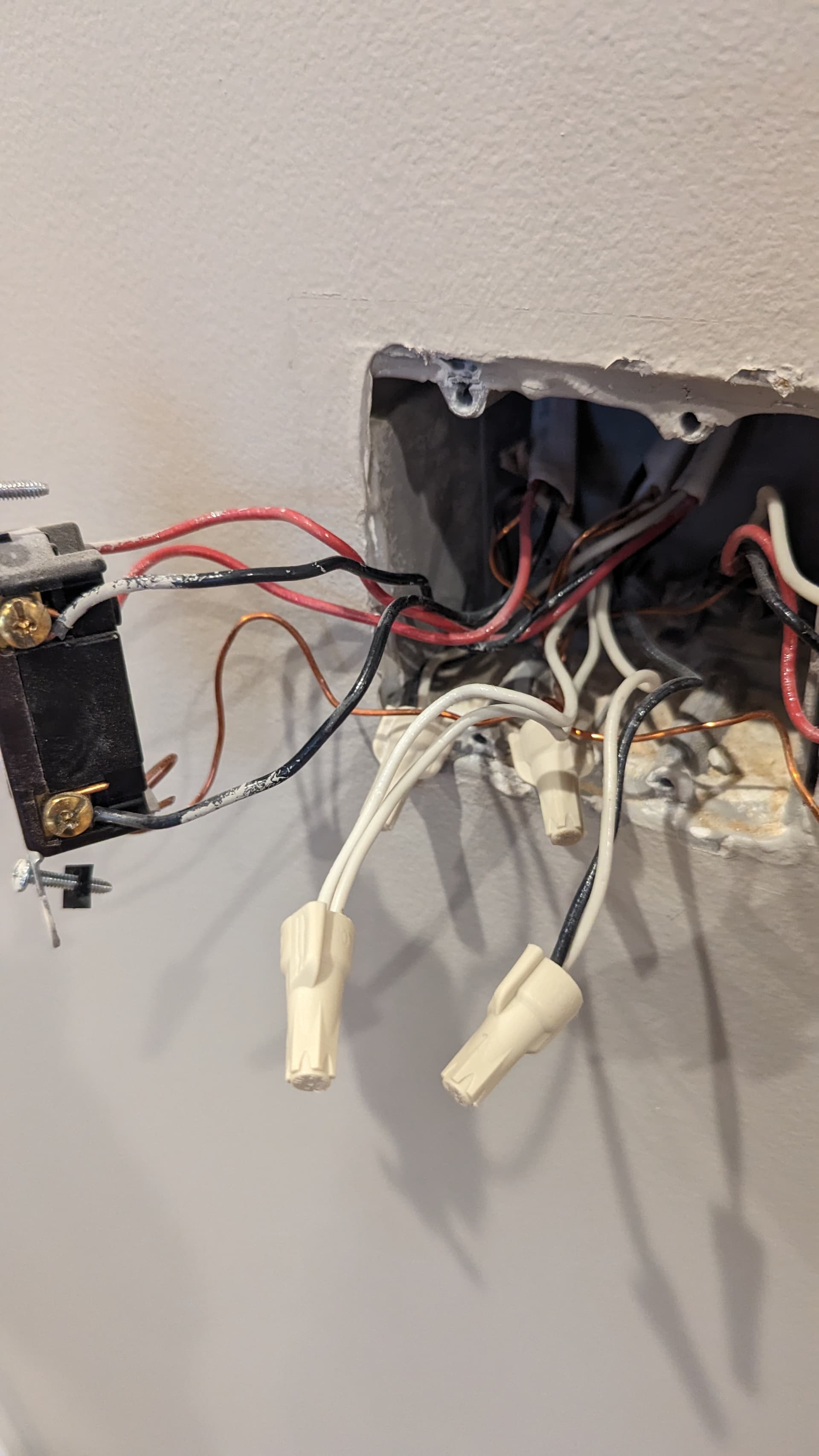
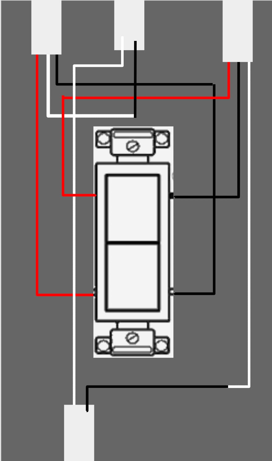
Can you confirm the connections to the 4-way switch in the picture? It’s a bit tough to see into the box.
I think I see two 3-wire Romex connected to the switch. The two blacks and two reds are connected to the switch as pictured. But are the two whites from those 3-wires connected together. I see the two wire nutted, but can’t trace them back to the two 3-wires in the picture.
Thanks, glad I asked. I saw the black/white connection but couldn’t trace it.
You’re probably correct regarding the 2-wires, one being line and one being load. The next step will be to determine which is which.
Separate the wire-nutted black/whites so that you can test the disconnected black conductors. Using a meter, test between a single black conductor and the bundled whites that belong to the two 2-wires (you can leave them bundled, just remove the wire nut).
Also, take a look at the two 3-wire switches and confirm that the white conductors are connected to the common/black screws.
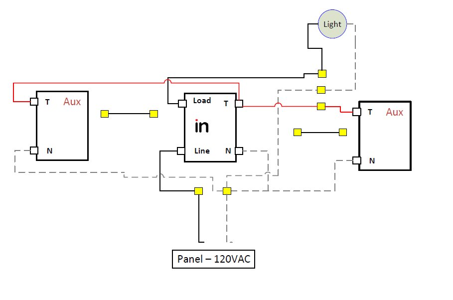
This will require Aux switches. I don’t think it’s possible with dumb switches.
The concept is simple. It’s essentially a 2-way Line/Load in the middle box. You’re adding Aux switches to the left and right. Aux switches need a neutral and a traveler (in a neutral configuration), so you use 2 conductors on the 3-wires to do that.
Don’t forget to configure the Inovelli as a 3-way momentary.
You can use smart switches in lieu of the Auxs. Instead of routing a traveler and a neutral to the two no-load switches, you’ll route a hot and a neutral, which go the the Line and Neutral terminals. You’re just sending a hot and neutral to power those switches without a load.
You’ll then need to link the switches to the primary by using associations (Red) or binding (Blue).
Ok, thanks. I’ll try that. I have a few places where I could hold off installing switches for now until I can get aux. This location is primary hallway that really needs to have smart switches.