I’m installing a Blue Series 2in1 Switch to control the lights in my garage and this switch lives in a 2-gange box with another switch that is a smart aux switch (lamps).
Also in this box seems to be a power and ground wire that powers my garage door. When I disconnected them the garage door motors didn’t work.
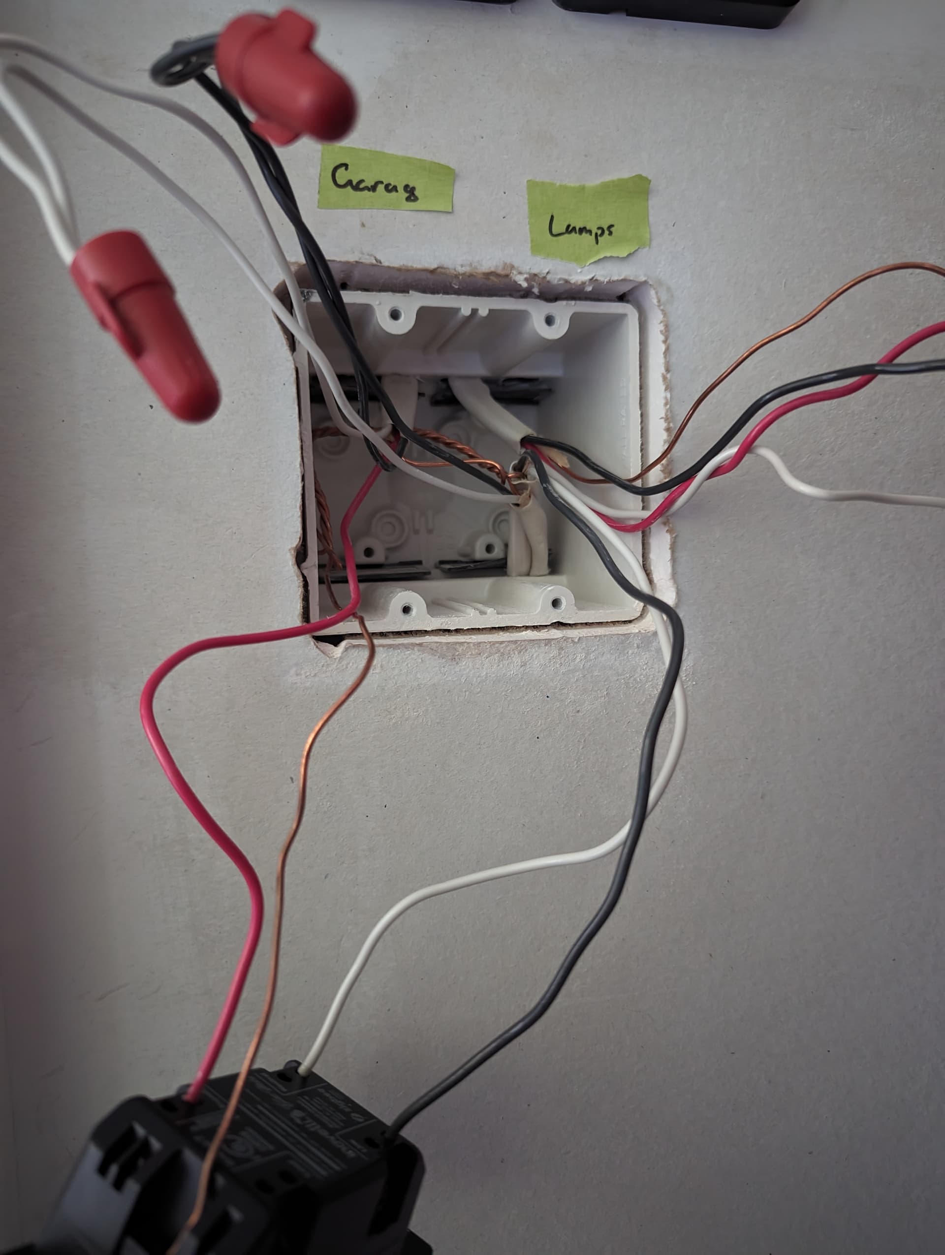
In this image you’ll see 2 3-wire romex cables coming from the top of the box. The one on the right is for the aux switch. Which I’ve wired and all is functioning as expected. The one on the left is for the switch in question.
From the top left 3-wire romex I’ve connected the red wire to the second terminal on the switch. I’ve connected the black and white to the hot wire and ground wire respectively from to the rightmost 2-wire romex black from the bottom right of the image. I believe this to be my garage door opener.
I’ve then connected the hot and neutral from the remaining 2-wire romex to the appropriate terminals on the switch. I’ve confirmed this as powered with a non-contact circuit tester.
Wired this way I get no power to the switch. If I put jumpers to the black and white bundles in the top left of the image to the black and white terminals I get power to the switch and the lights will respond to the switch by flicking on and back off while the switch is still in the on position.
I’m expecting one of these black wires needs to be in the load terminal but I can’t decipher which.
Are your garage door opener (GDO) and those lights each on separate breakers? My guess is those 2 14-2 romex coming in from the bottom are each from different breakers. If true, you don’t want to be co-mingling any wires between them.
When I switch off my ‘garage lights’ breaker no wires receive power and my GDO buttons don’t function. Not sure if the opener itself functions now that you’ve made me think about that.
My thought there is that the 14-3’s black/white is line/neutral for the opener, and the red is load to a light fixture (that’s getting its line/neutral some other way). But that feels like I’m grasping at straws…
So that Aux is working fine now using just the 4 wires from that upper-right 14-3, correct? What terminals are the 14-3’s red, white, black wires attached to on the Aux switch?
I’m still stuck on why there are 2x 14-2 coming in the box (but seemingly just one breaker involved)… There’s significance to that, but just gotta figure out what it is.
It’s totally up to you as to how to proceed. If you are in over your head, it may be best to call an electrician.
You’ve probably already figured out that it’s best to document the working configuration as a first step.
Also, when you are installing a multi-way switch leg, you need to inspect the connections at ALL of the switches so that you understand the wiring topology. You can’t just go to what you think is the first box and start wiring, as what happens downstream will impact the wiring. I’m mentioning this because you were connecting to a 3-wire, which more often that not involves a multi-way, and it does not look as if you’ve given any consideration to the other box(es).
Your topic suggests this is a 2-way. Are you sure there isn’t another switch?