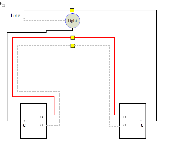
I’ve got a 3-way with no neutrals in the switches, and the power coming into the light, seemingly between the switches. I received a red series to use for a dimmer for about 48W of power. The light box is relatively inaccessible and so I’m trying to figure this out from the switch boxes alone. My GANGBOX wiring looked like the classic version on buildmyowncabin that I see posted, with the exception of one box has the red and white reversed. Nothing is marked with tape, etc, and other than knowing the light box definitely has the power, I’m unsure about what’s going on inside. The 3-ways did operate correctly before. The only neutral in the double-gang (what I think was similar to the left in the diagram below) comes off a different leg and is capped off. A modified drawing is below.
So, I tried wiring similarly to before, but to no avail, before I realized the power was into the light. From my understanding I needed a Aux switch rather than a dummy, so I bought a GE [46199]. How should this be wired? Can I tell without fighting the inconvenient and difficult to remove light fixture?
You don’t have to get at the light, but you do need to figure out which of your two boxes is getting the power first. If the drawing your posted matches your wiring (don’t worry about the red/white being switched), then you are looking to identify which of your boxes matches the box on the right.
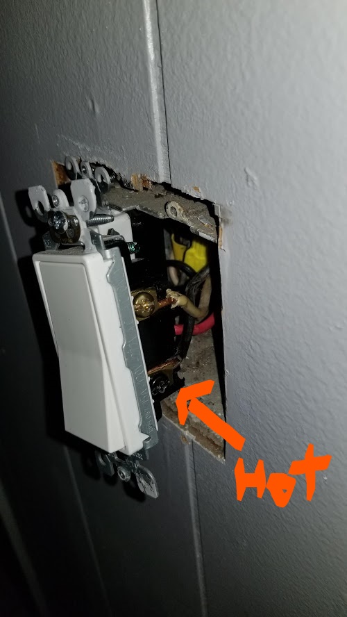
Pull your existing switches and confirm that the black conductor from the 3-way is connected to the black screw on the switch at each location. Remove the black conductors from the switches and using a meter, test between the disconnected black and the copper ground (or your metal box if that’s what you have). One of those two blacks with be hot and the other won’t (with them both disconnected).
Once you have confirmed that, post back. It really isn’t complicated. Basically, you will wire the box with the constant hot as a non-neutral and then factor in the Aux in the other box.
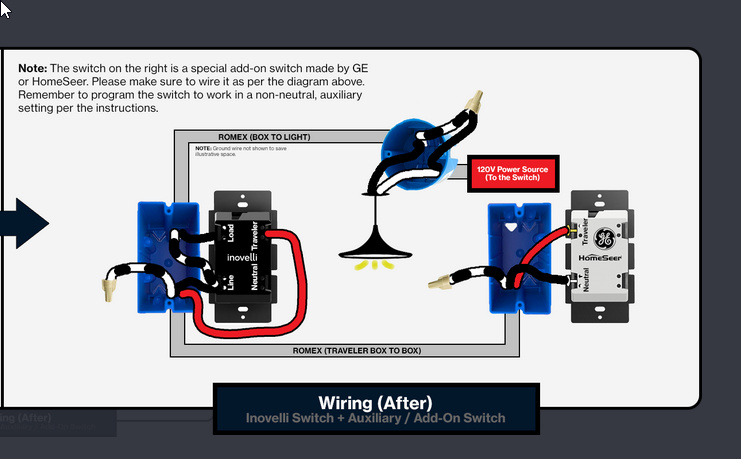
We’ll use this as a reference but it won’t exactly look like this:
Ok, I can’t see inside your box . . boxes for that matter. In each location, are all three conductors attached to the switch coming from a SINGULAR 3-wire Romex?
You’re awesome… thanks. I’ll be sure to wait… definitely want to get this right, and NEED it to work. Had changed the lights to 8W edisons and the combined 48W of 4000K light at full throttle is a bit disorienting to say the least.
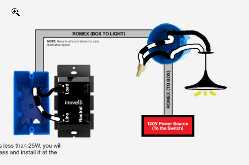
j/k The good news is that this is doable. The bad news is that even though didn’t have to get at the light to diagnose, I think you are going to have to get at the light box (or the first one since I think you have multiples) where the power is being fed from.
The reason for this is that for this to work, we have to wire that box getting power first as a 2-way non-neutral. The Inovelli is going in the box that is getting the hot. This requires wiring the black hot to the Line terminal of the Invovelli. That’s easy. The bad part is that the Load on the Inovelli has to be fed back to the light. You have two conductors going back to the light box, but they are presently passed through to the other side. We have to convert one to connect to the light.
You are also going to have to send a hot to the Aux box, and that will have to originate from the light box as well.
Well, I have good news and bad news, too. The good news is that it’s only one box (the light fixture/feature itself has the parallel wired lights). So, there’s no confusion on what box to get at. The bad news (for me, you’re fine either way… ) is while it is not that physically inaccessible, the fixture is a pain to remove with multiple supports and I have thoracic outlet syndrome, with my back already acting up. So, getting my arms above my head tonight probably isn’t happening. Even if I open it up, if memory serves, there’s no clear indication of what romex leads where and it will take some testing to figure out which wires are which. If it was straightforward, I might be able to hack it today, but, my arms will be dead before I can get halfway through. I’ll have to close up the boxes and do it on a healthier day. I appreciate the help.
This would have the Inovelli Red acting as a single pole non-neutral and limit functionality (that I may or may not even use… just follow me for a second) and the GE is acting as a wired remote communicating through the neutral. From your diagrams, it doesn’t seem that the switches would be in any way wired in series. Is there anything that keeps me from installing the Inovelli as a neutral-present setup, with the red wire flagged with black tape as the load going back to the fixture? Would that mess up the communication of this particular Aux switch? If the neutral is possible, why not use it? If it is possible, do I just tie in the romex from the aux switch directly to the hot and neutral, capping off the red as shown?
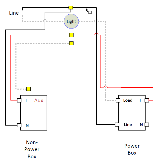
I’m not sure I totally follow your question. Right now, at least as per your diagram, you don’t have a neutral in either box. The neutral stops at the light. To complicate things, the Line is in one box and the Load is in the other.
I didn’t show you the whole diagram, but the way this works is that we first wire the box with power as a 2-way non-neutral. To do that, you would use the white from the 3-wire to connect to the light. To connect the Aux, which needs 1 traveler from the other switch and a hot, we’d use the red from the 3-wires for the traveler and the extra white from the 3-wire in the Aux box to get the hot from the light box.
So in the light box you would have to connect the white to the light, removing the black from the Aux box. The black that you just removed would then be connected to the hot in the light box to send power to the Aux.
That’s how the whole thing would work. Post back with your question, though. Maybe with a bit more explanation we can work something out. I can draw up the full diagram tomorrow too, even if you don’t wind up using it right away.
Alright, I think I understand what was wrong with my plan, based off misunderstanding your previous post with the partial diagrams. If you have the time, I would love a full diagram. I instantly get your simplified schematics, where-as the fancy graphical ones tend to make me stop and second-guess what’s happening.
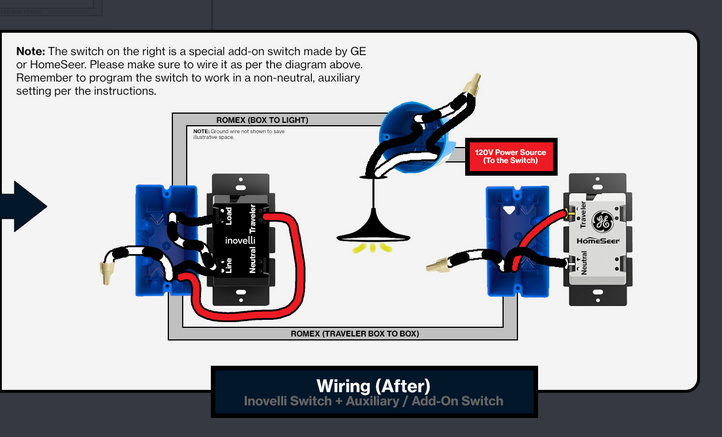
Looks good. Depending on how the electrcian wired it in the light junction box, may be a different color than show between @Bry or Inovelli’s diagram. Just be mindful of that. No need to rush especially if you’re not feeling 100%.
Also, just remember the bypass will need to be connected between the BLK and WHT lines that are connected to the light (LOAD coming from switch)and neutral. NOT the LINE from the source.
I don’t know your situation, however being the homeowner, you could elicit the help of a friend or neighbor to perform the changes in the ceiling light. He/she need not be an electrician. But the responsibility for being correct will be yours.
On the plus side, as long as the connections are well made and wire nuts are on tight you should have no reliability / safety issues.
Sorry I hadn’t gotten back–had gotten very busy and have been nursing my injury a bit. Was thinking about this again in the shower the other day and had had a moment of clarity regarding the wiring. Your diagram matches what I understood from your mashup of directions and snippets of other diagrams. I appreciate the extra work, to be sure. Going to yank down the lamp now and have at it. Hoping I don’t need the bypass but will check things before replacing everything. I also remembered that you were right in your thinking that there might be other legs running off this junction, as I do recall seeing more neutrals tied together than would otherwise be here. It’s a tight box, but if I can see the romex, I should be able to flag the lines already coming from the two gangs boxes from the established wiring, making identifying the rest of the wires unnecessary. Appreciate all the help (and the confirmation from everyone else). Here goes…
Thanks–seems I do need the bypass. Everything seems traced, wired correctly, lines are hot, travellers seem to be at 24v (is that what they communicate at?). The only thing I can’t figure is that replacing the LED on the cheapo temp lamp I hooked up to test before reinstalling the awkward one didn’t bring the Red Series to life. I have a couple others installed (in neutral setups) and could pull one to test if I somehow got a bum switch I need to RMA, but trying to double-check everything else first.
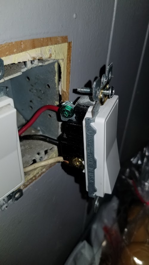
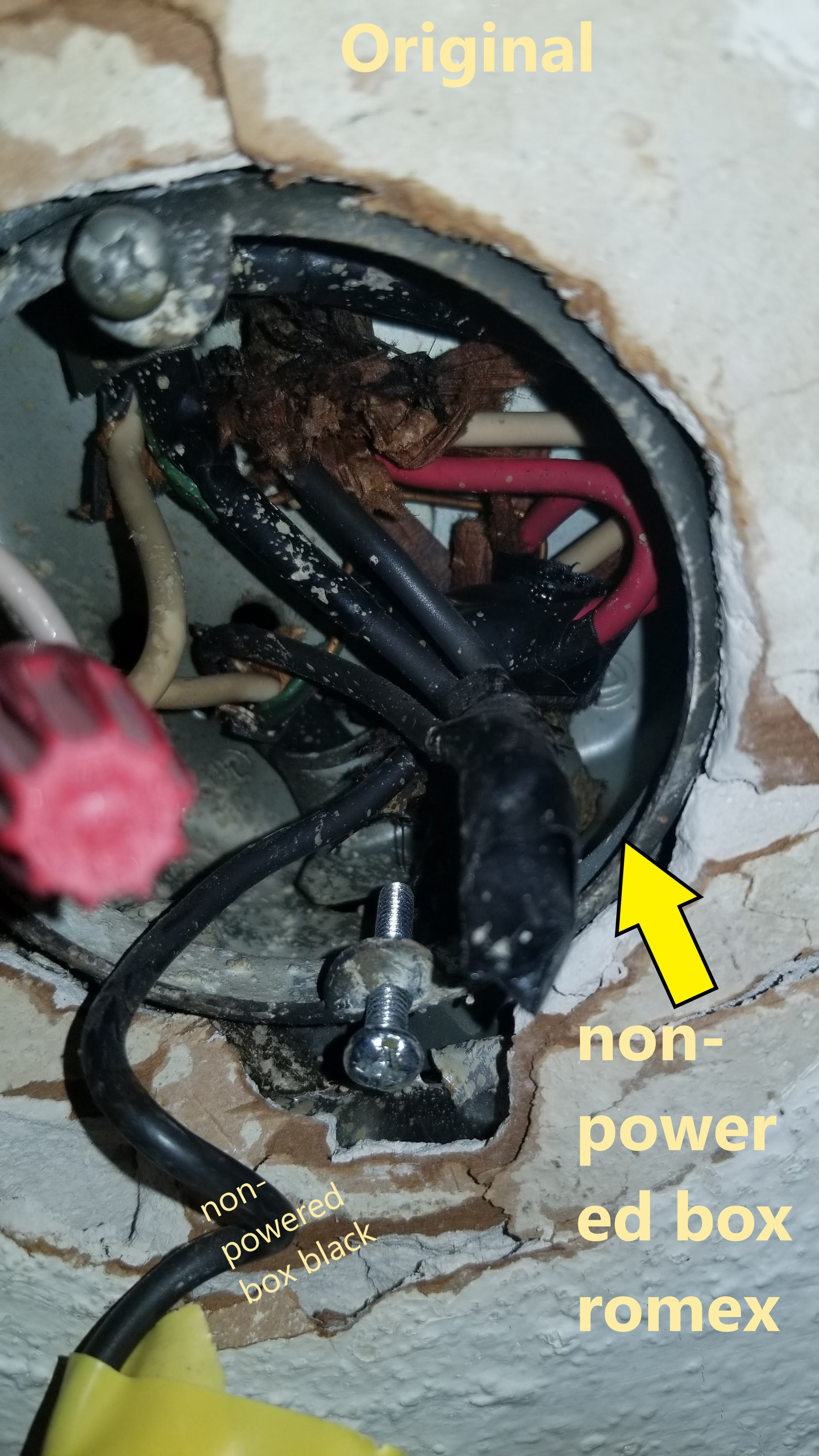
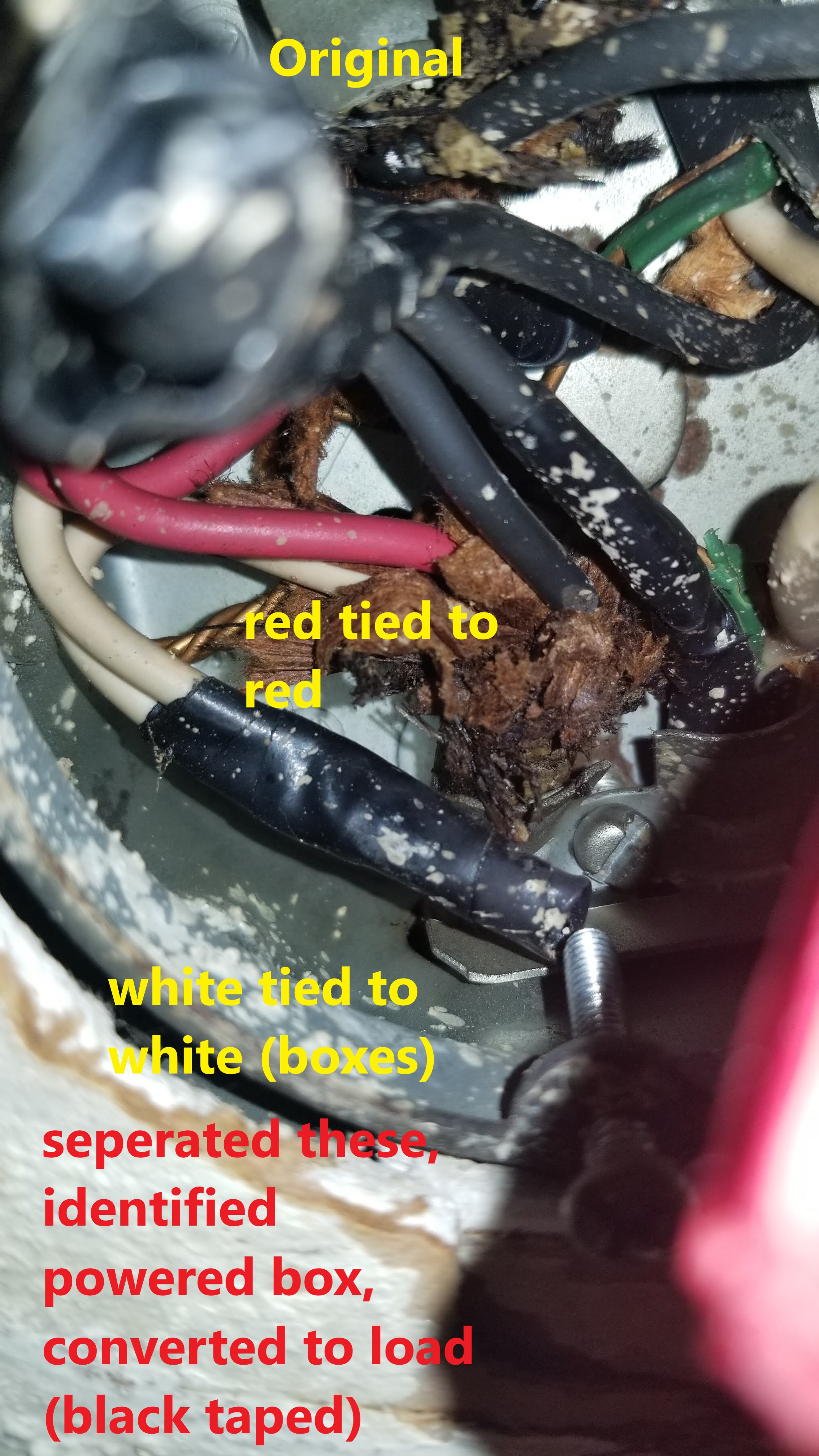
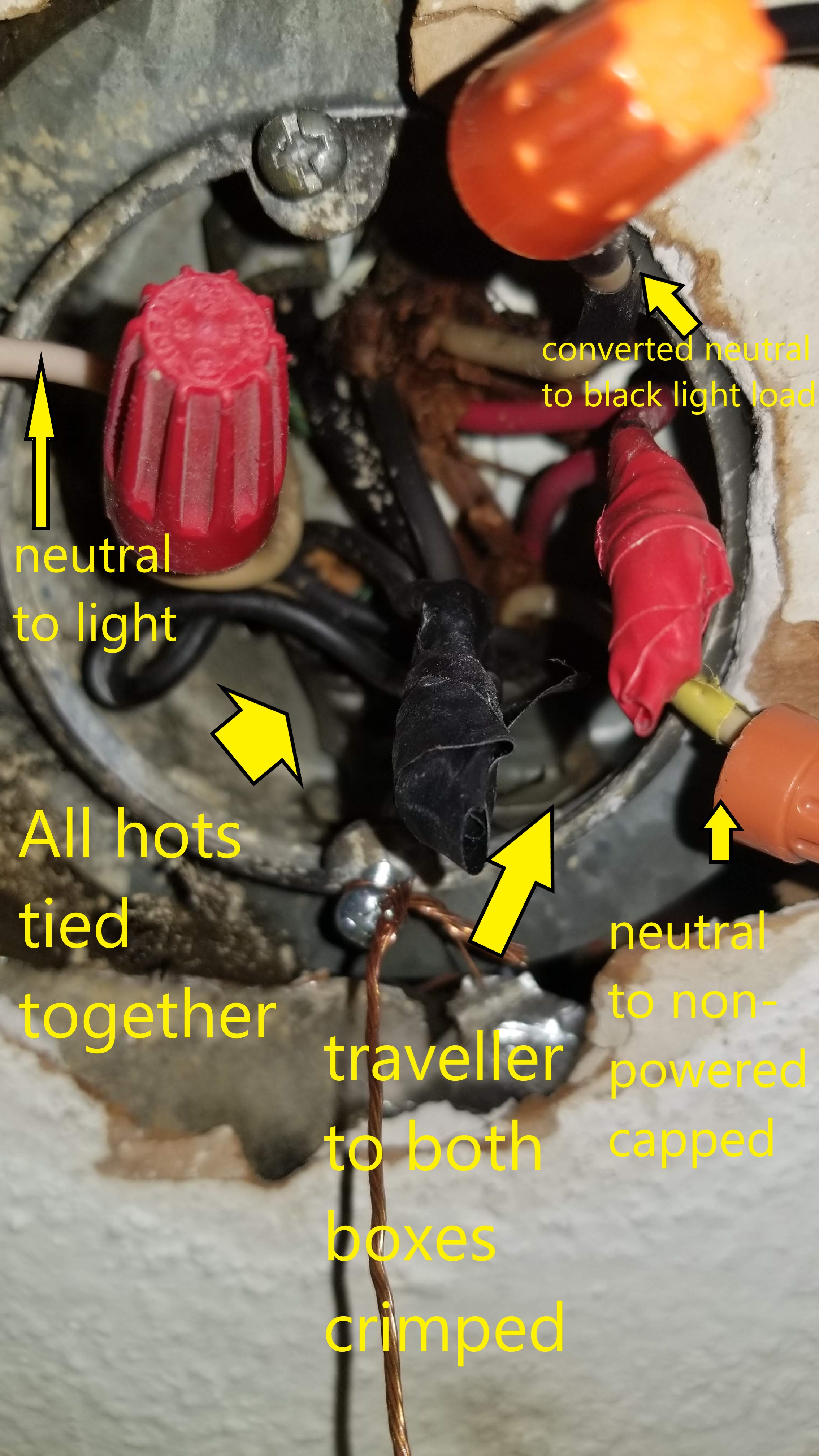
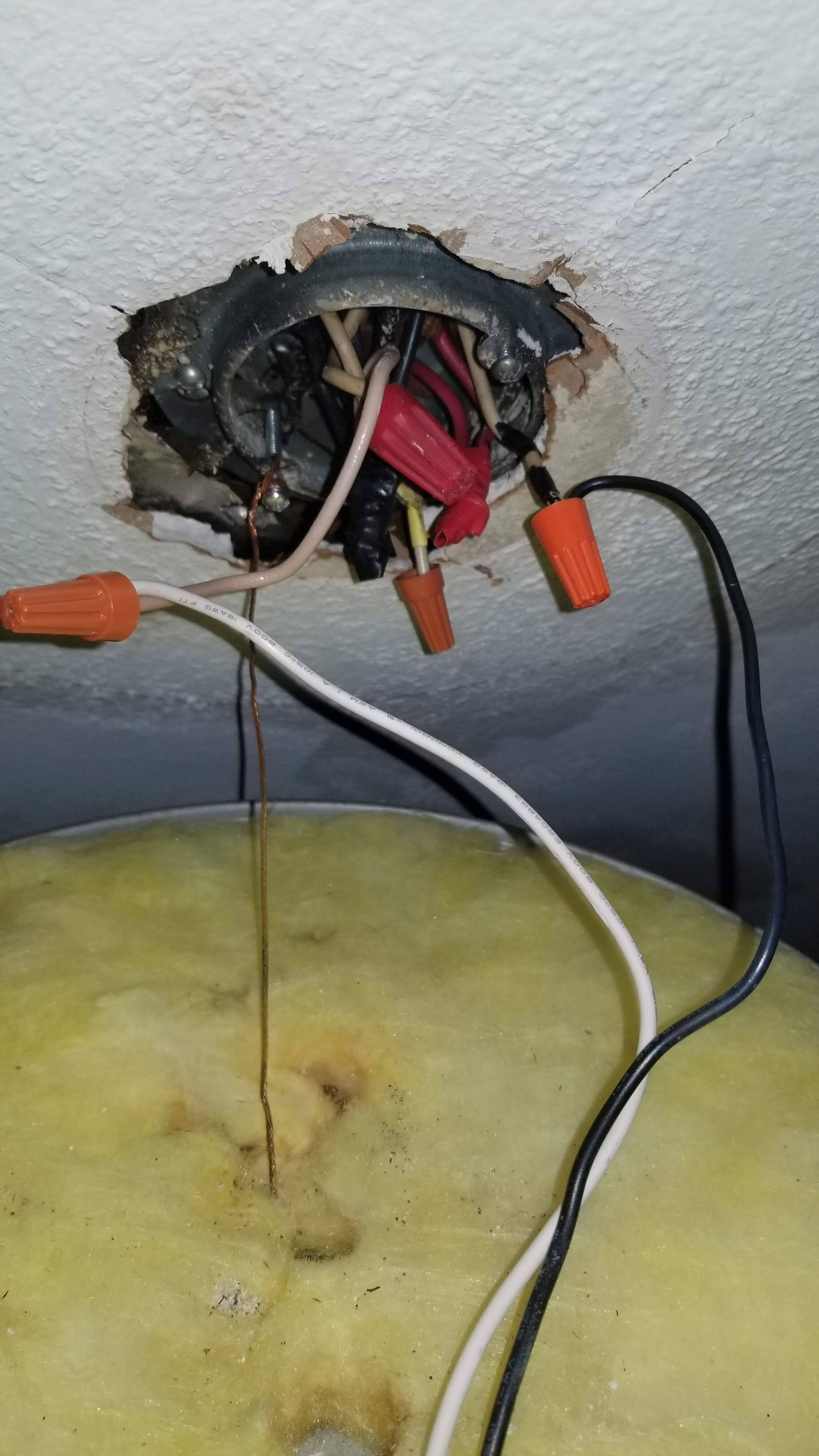
Below are some photos… the before had the red travellers and the whites tied together, just as you suspected and the conductivity test confirmed. I pulled the two neutrals, identified the one that went to the powered box, and taped it off as a black return (load) on both ends. That’s hooked up into the load on the Inovelli. I had to uncrimp 3 blacks, which I added the 4th to (from the light previously, which I confirmed goes to the non-powered box–now providing a hot black), crimping them up and rewrapping in tape. The hot is connected to the Aux neutral, and the travellers are connected on both switches (and still tied together in the box). The neutral from the line still goes to the light fixture (white), with the other lead (black) connecting to the neutral (taped and converted to return load) from the powered box. The white neutral to the Aux in the old non-powered box is capped at both ends.
Testing the hots at the switch, I get 120v. LED or incandescent (60W), I get no response on the Red Series. I’ve pulled the air gap, pushed it back, and still nada. Wouldn’t expect anything to be in inclusion mode, but searched using the Hubitat anyway to no avail. I had to reassemble everything (except the big lamp) for the evening for safety for the kids tomorrow, but will have at it again if I get any leads. As I said, I could pull another Red Series (though I’d rather not, of course), and I ordered a Aeotec bypass just in case but it won’t arrive until Thursday.
So, the question has become… did I do something stupid, is it just a neutral/bypass problem, or is my Red Series malfunctioning? I suspect I’ll know more by swapping around the switches, just was trying to avoid the chaos if possible… it’s rare that both of these sections of the house can have the breaker pulled and not affect somebody’s schooling or the wife’s attitude. She’s pretty easy going about home improvement inconveniences, but I think she’s over this particular wiring project.
I can’t really very your wiring from your pics, but a couple thoughts.
1 - Use and incandescent bulb to test. That should work without a bypass and allow you to determine if the leg is working properly. If you have to, go get a lamp socket and wire it in temporarily.