I installed 9 Black Series dimmers this week, tying to the neutral “bundle” located in each multi-gang box. 7 worked great but 2 cause the breaker to trip as soon as I turned it back on. It’s a brand new house and there are GFCI and Arc Fault/GFCI breakers in the panel. The 2 that are tripping are on different Arc Fault/GFCI type breakers. Neither of these switches are 3-ways. Any ideas short of going the BYPASS route? Thanks
Try connecting just the dimmers to the source neutral and see if it still trips.
How do I determine which of the 4 white wires in the neutral is the source? There are multiple circuits with neutrals in same bundle. Thanks
@rlhiggens - Depends how many wires you have. If there’s a lot, you’ll need to separate the black bundle and find “LINE” from the panel with a voltage pen or multimeter. The WHT wire that is paired with the BLK that has constant hot will be the LINE. Sometimes electricians will mark the others or use other identifying measure to help. Obviously, you can rule out any of the BLKs that are connected to the other switches in the box.
Are you sure about that? That would violate the NEC and I doubt that a competent electrician would do that. Plus that alone could cause issues with AFCIs. Unless the switches are faulty, there is likely another problem.
Just exactly what is the source neutral? Do you mean just connect it to the white in the 2-wire Romex that’s supplying the power?
The bypass won’t solve your issue. It’s used in non-neutral situations and some others related to LED issues that are unrelated to breakers tripping.
@rlhiggens Can you post pics of the switch and the box so that the connections and wiring into the box is visible. We’ll be glad to take a look. Let’s do one at a time.
Yes it’s a very full, 4 gang box. I did separate the 4 white wires and tried each one to the dimmer. The result was only 1 arc fault breaker tripped as opposed to 2 different arc fault breakers tripping when the bundle was together. I really believe these arc fault breakers are getting some kind of voltage associated with the dimmers causing them to trip. Maybe the bypass is the easiest solution. I’ve looked here at that discussion and found someone who said you can wire the bypass at the switch end, complete with great graphic picture. This would work for me better than accessing the light end.

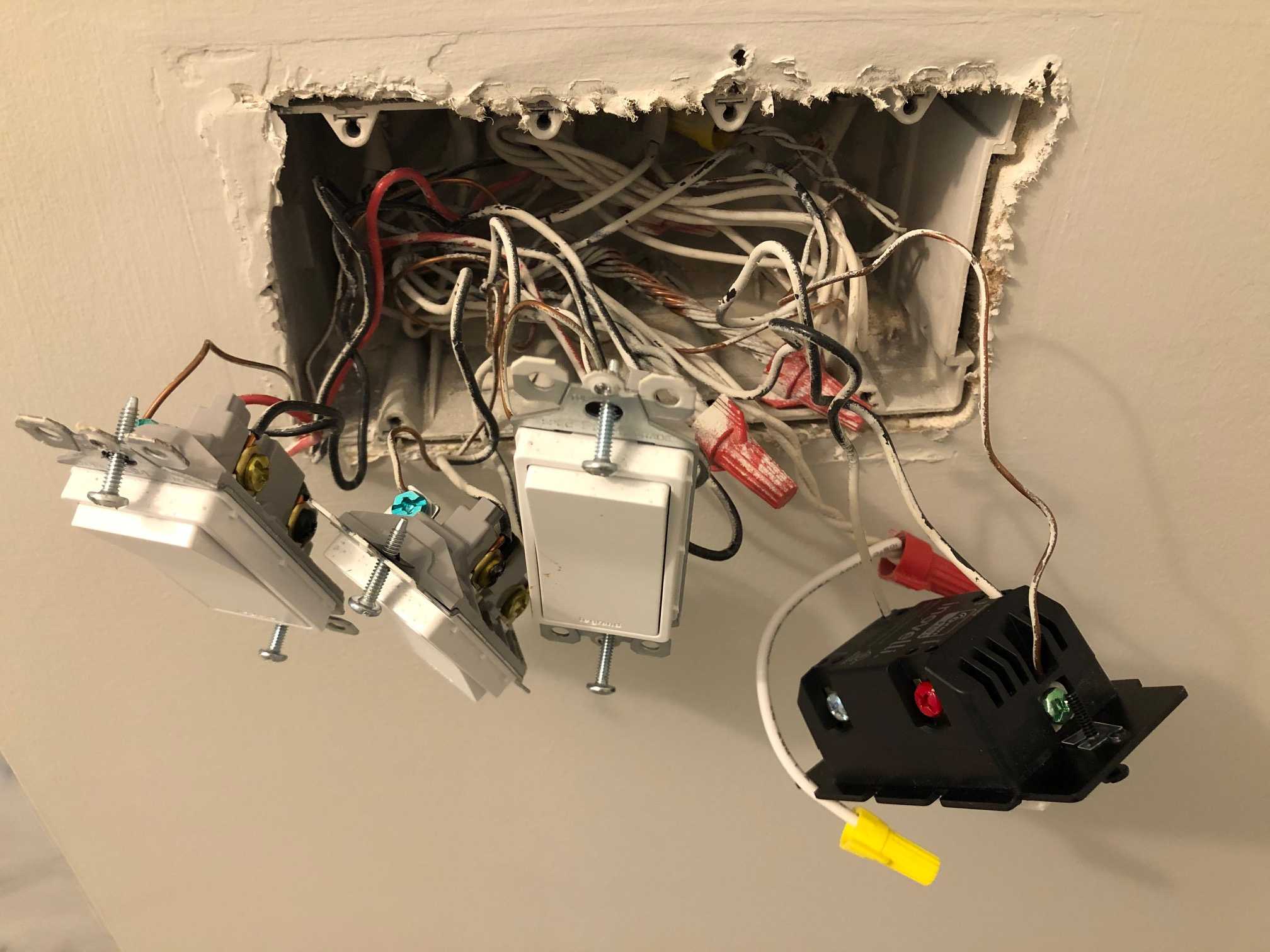
I just love painters that can’t stuff a box before they spray the wall! 
But I digress . . .
A couple things to check. I see 2 neutral bundles in that box, so make sure that the 2 conductor neutral bundle you are pigtailed to matches with the black Line. This is what @harjms was getting at.
Confirm that the black conductor you have attached to the Line terminal is a constant hot. I presume you already did that. Now follow that black conductor into the box and find where it’s coming from. I can’t see it in your pic, but it’s either going to be a single Romex or a black bundle. The goal is to identify a white conductor that is either the other conductor in a single Romex or one of the Romex contributing to the black bundle (whichever you have). Once you identify one of those neutrals, make sure you are pigtailing to that neutral bundle.
You have a 50-50 shot. The other neutral bundle is in the back of the box. (I can’t see into the box to tell, but hopefully that small neutral bundle in front isn’t connected to the big one in back, which might be what you were alluding to.)
Also, do the same thing with the ground. There are two ground bundles in the box. You want to find the proper one using the technique described above.
I think there are two circuits in that box, which is OK. I see two ground bundles as well.
I have a number of Inovelli devices on circuits with either AFCIs or GFCIs and none of them have ever tripped.
1 Like
BINGO! I was in the process of documenting what circuits were tired together in these boxes when your reply came in. Sure enough there are 2 bundles of whites in each box and I just grabbed the closest and never looked deeper into the abyss! Now I have to look at the bundles of grounds. But now they are all working! Nice catch, thanks so much!
Like @harjms said, connect it to the neutral for that power source.
You probably have multiple circuits in that junction box, like one for the lights, and one a switched outlet (thus GFCI/AFCI, which are only required on outlets). That said, the neutrals from the two circuits SHOULD NOT be gathered into the same neutral bundle in the junction box. Only ground should be tied together at the junction box; neutrals shouldn’t connect until the (sub)panel, or you could turn off circuit A and get zapped by a neutral wire on circuit B still carrying return current from devices that are running. I’ve been zapped this way while working in a junction box, because the builder of my house made exactly this mistake!
The reason AFCI/GFCI trips in this case, and others do not, is that GFCI compares the current going out the hot to that returning on the neutral. If there’s any missing, you have a ground fault: some current found an alternate path to ground; which might have been through the ground wire, through some other circuit’s neutral, or through a human… which is what GFCI is protecting against. When you connected your switch’s neutral screw to the other circuit’s neutral, tiny amount of current used by the switch electronics is leaked, and trips the breaker.
Try to find the neutral for that circuit if you can. If this is a switched outlet, you might not have one: for switched outlets, the outlets are usually wired in the usual way, daisy-chained off the second set of screws. For the switched outlet (usually installed upside-down, with the ground holes at the top), the copper tab connecting the two “hot” screws is broken off (a “split outlet”) and a cable is run from the outlet to the switch. Because builders are cheap, they often pull 18/2 for this, sending the line-side “hot” to the WHITE conductor, and getting the load-side return from the switch on the black… instead of spending a few cents more per foot for 18/3 and using the red/black conductors for the hot coming/going and saving the white for neutral. BE CAREFUL: when a white conductor is used to carry “hot” like this, it should be so marked, usually by wrapping the wire in black electrical tape in the last few inches… and many builders don’t do this!
If this is the case in your house, you’re going to have to use the non-neutral option. Or do it at the outlet: I ran into this for an on/off switch, so there was no non-neutral option. I wound up installing an Aeotec Nano Switch behind the outlet (they’re really small) and using the existing run from the outlet to the switch to make the dumb switch be an “external switch” (COM to S1 connectors on the Nano Switch). It works: I can control the light with the switch or Z-wave, but it doesn’t look as good as Inovelli. ![]()
Two little tidbits out of the National Electrical Code you ought to be aware of, assuming this is for an outlet, even though I’ve never seen the required hardware/markings in the wild in a residential setting.
- The receptacle should be marked with the word “controlled” the on/off symbol (like on a computer’s power button). This is so people don’t plug something that needs to remain on (like a computer, or medical equipment) into an outlet that gets turned off automatically… I’ll eventually get marked outlets (e.g., Leviton CR015-1P…), but for now the existing ones are marked with label-maker tape.
2017 NEC section 406.3(E) requires:
(The figure is the usual circle-with-a-line-through-it on/off symbol)
(Yes, there’s an exception for “receptacles controlled by a wall switch that provide the required room lighting outlets as permitted by 210.70”, but that might not apply since the receptacle is now controlled by the switch AND Z-wave.)
- Dimmers SHOULD NOT be used outlets, only “permanently installed luminaries” (i.e., light fixtures), as will be written in the dimmer’s instructions somewhere. This is so someone doesn’t plug a vacuum cleaner into a dimmed outlet… There is supposed to be a special, incompatible, plug and outlet pair used for “dimmed” outlets so that only a lamp or other dimmable thing can be plugged in. Lutron makes such a thing (NTR-15-HFDU…), but I’ve never seen it in the wild.
2014 NEC section 406.15 requires:
Good luck, and be safe @rlhiggens .
Turn the circuit(s) off, and then check every single wire in the junction box (yes, even the white and bare ones) with a voltmeter or inductive tester, before you touch it, every single time. I’ve had many adventures dealing with the wrong, lazy, out-of-code (even for the time), and sometimes downright dangerous mistakes made by whatever “professional electrian” (presumably, the lowest bidder) was hired by Centex when they built my subdivision. I’m frankly surprised some of the errors I found passed inspection. Basically don’t trust the other guy’s electrical work—I learned that lesson the hard way, more than once, by getting zapped. 120VAC hurts; I’m glad I’m not in Europe…
1 Like
Good! Glad you got it going!