Hello, I am new to inovelli. I have two other z-wave switches on 2-way circuits. My challenge, I am wanting to control the lights on my back deck but, five of the entry points to the back deck have a switch controlling the lights. I am not really savvy and more like a little gun shy when working with wiring to I was wondering if anyone has a solution for this situation. I skimmed the existing posts and did not see anything. Thank you for any help.
Welcome to the community, I’m sure we can help you.
So to be clear, you have 5 switches all controlling the back deck lights, in a configuration that you can switch the back deck lights on or off from any of the 5 switches. Am I correct?
John
Yes… My house is U shaped and everything opens onto the back deck. Each access to the back deck has a light switch. I am hoping to find a way to integrate the back deck lighting into my overall home automation solution. I need to understand how to implement switches. Everything I have seen is limited to 3-4 switches.
Once you go beyond 3 switches, everything is the same-- just more 4-way switches in the middle! So you just need to follow the 4-way installation diagram in the manual.
Your switch circuit will be a 3-4-4-4-3. Note in the diagrams, you have to install the Inovelli switch at the position closest to the power source. Otherwise the switch will lose power when dumb switches before it in the circuit are toggled.
As seth said 4-way to 5,6,7 even 10 way is all wired the same.
Question:
Is a smart dimmer in one of the end locations with the remainder plain ON/OFF switches acceptable? It is the least cost, least wiring change solution.
HOWEVER, if the dimmer is set to bright and you want a romantic 30% you will have to go to the dimmer to make the change as the other switches can only control ON/OFF
Alternatively, you can replace the other ON/OFF switches with Aux switches. This will allow you to control the dimmer from ANY of the 5 locations.
Whichever solution you pick you will have to find at which switch the power is entering the circuit.
IMPORTANT Note:
In any descriptions of the number of wires, there may be an additional wire. It will be bare (no insulation) or green. We do not count this wire in any mention of the numbers of wire going to the switch. This wire is the safety ground and goes to every switch and receptacle but is not part of the switch function.
Unless you have a meter that can measure 120 VAC I would suggest you purchase one of these or these . They are actually better than a meter in this case as you don’t need 3 hands.
- It will be at a 3-Way switch.
- A 3-Way switch has 3 wires in the back
- A 4-way had 4 wires.
- Find the boxs with the 3-Ways and post a simple sketch of the wiring inside. I usually use dotted lines for white, again don’t bother with the bare wires as they only confuse the diagram. Photos can help as well.
Thanks for the info. Still collecting data. Attached is a snip of my back deck circuit and pics of the rightmost switch and the next one in. Of note, the rightmost switch is a 4-way switch. The next one in is a 3-way but, I did not see the line in power. I really thought these switches would be in order but, obviously it is the line that establishes the circuit and not the shape of the house.
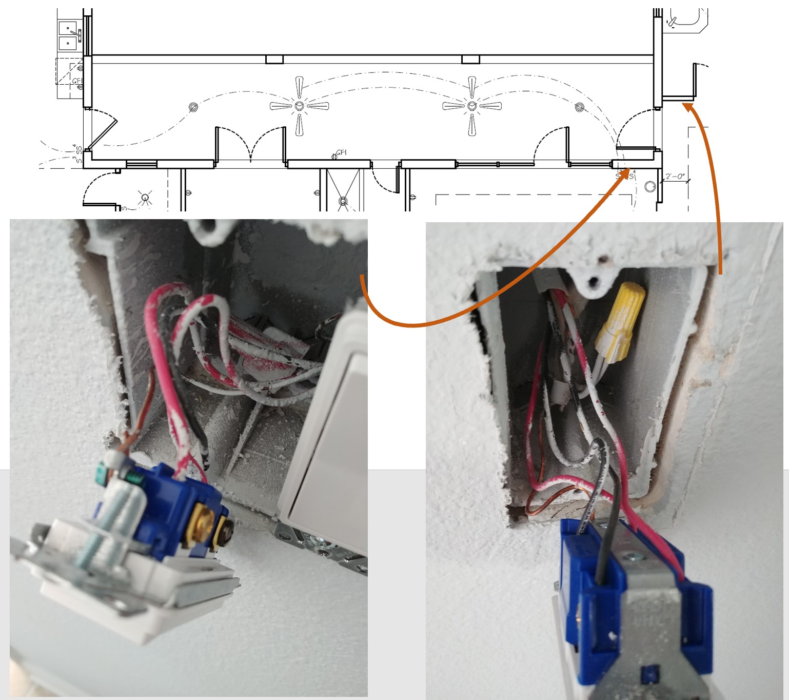
OK… correction… looking at my pics and a normal four-way diagram, the pic above the three-way switch could… or could not be the switch with the line-in power. Is there any simple way to identify if this is correct switch to replace with the inovelli smart switch?
Is there any simple way to identify if this is correct switch to replace with the inovelli smart switch?
I don’t know about quick but there are so common expectations:
- The line is almost never at a 4 way switch.
- A 3-way must have at least 2 cables entering the box.
- Unfortunately, the power line doesn’t necessarily enter the circuit at a switch box.
I would look next at the far left switch.
Will do… One question, in a four-way circuit, any of the interior four-way switches can break the circuit to the lighting. So, if I opened up the boxes I showed in the post above and turned any of the interior four-way switches off, I would think I could test the inputs on the three-way I identified. If there is power on the incoming black wire I think that should be the line-in power. If there is no power, that would identify the line going to the lights…??? Does this make sense???
Exactly, and switching any of the 3-ways will do the same.
BTW 4-ways (and 5,6…ways) are really quite easy. Its just when you are looking at a closed switch it seems mysterious.
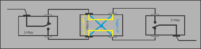
You can print a few out, switch the switches and trace the power / open through the series.
A 4-Way switch simply reverses the wires (or not).
John
Sorry for the delay in getting back. I was out of town and down with the flu.
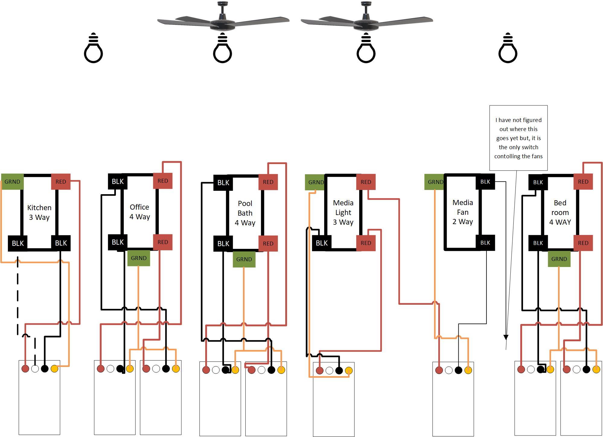
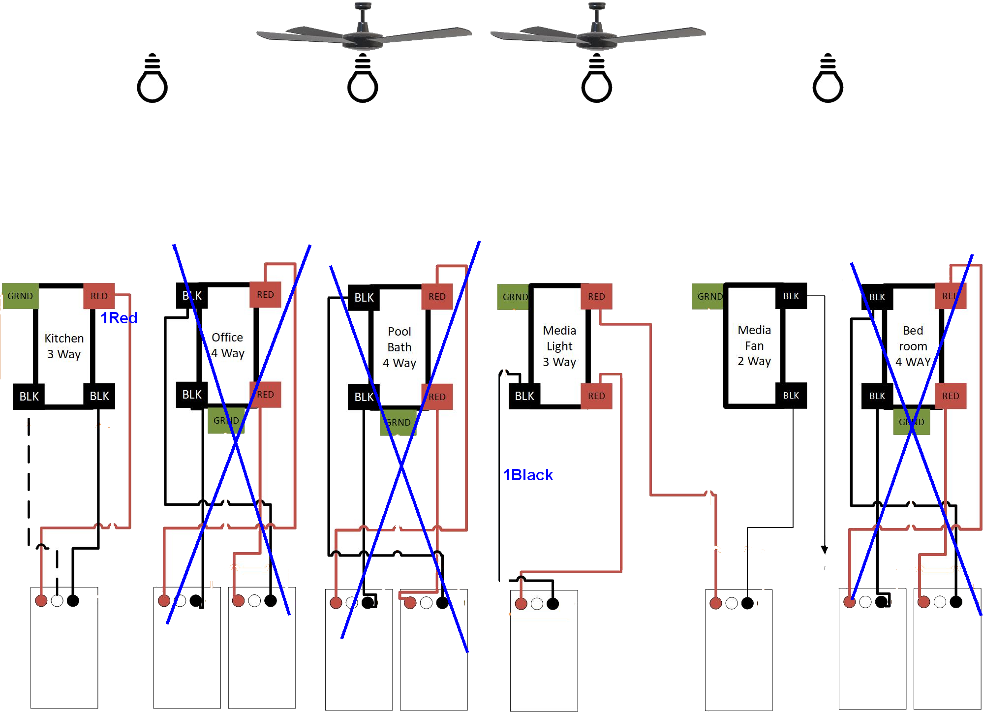
Well, the plot thickens. Attached is a pdf showing the connections at each switch. Unfortunately, there is some added complications and I have not determined where the power in line is. Please take a look at the pdf. I am interested in your thoughts.
While I continue to hope to solve the above… I also tried to install an LZW30 in a four switch box… and failed. I forgot about the heat sinks and it would not fit. There is a very brief statement in the instructions I downloaded but, I could not see a quick and safe way to remove them. The instructions state that they can be removed without any negative impacts to the switch but, I did not see any details as to how… your guidance is appreciated.
So I understand, Each switch represents a wall box, and the squares with dots each represent a romex cable.
i.e.
(I removed the grounds on the copy I have to keep the wiring simpler)
Questions:
-
Do these boxes only have the switch you’ve drawn or are there other switches in some that are not shown.
-
None of the 4 way boxes have the white connected. Are the left open, or (more likely) connected together.
-
Should we assume the media light and the media fan are in the same box?
-
The media fan black wire that you cannot identify where it goes, I’m not being argumentative but why not? Is it going into some other cable not shown?
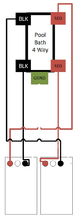
In the meantime, I think it is best to ignore the 4-Way’s and concentrate on the 3-Ways.
I think the power is coming on on 1BLACK or 1Red. 1Black is most likely the best guess (IMHO)
So if you have a meter or voltage tester:
Disconnect 1Black from the Media light switch.
Monitor the 1Black for power
Switch each switch one at a time. If after all the switching the 1Black continued to have power then we’ve found the power.
Else repeat with 1RED (reconnecting 1Black.
John
John,
Thank you for getting back so quickly. The following are responses to your questions as best as I can do it.
- Do these boxes only have the switch you’ve drawn or are there other switches in some that are not shown.
a) Two of the switches, the Kitchen switch is co-located with two other switches controlling the interior lights for the pot lights in the kitchen and the dining room ceiling lighting. - None of the 4 way boxes have the white connected. Are the left open, or (more likely) connected together.
a) All the neutral lines are twisted together. Sorry I did not illustrate that. - Should we assume the media light and the media fan are in the same box?
a) Yes.
i) The media room box has 4 switches (the TV room) are in the same box. This box has switches for:
(1) the pool deck lights,
(2) the pool deck fans,
(3) the center ceiling light,
(4) the switched outlets that are behind the crown molding in the stepped ceiling.
ii) The kitchen room box has 3 switches:
(1) The pool deck lights,
(2) The kitchen ceiling pot lights,
(3) The dining room ceiling light fixture. - The media fan black wire that you cannot identify where it goes, I’m not being argumentative but why not? Is it going into some other cable not shown?
a) Sorry, I guess the better way to say it is that it goes to a separate Romex cable. I have not taken out the other switch to trace the cable.
In the meantime, I think it is best to ignore the 4-Way’s and concentrate on the 3-Ways.
I think the power is coming on on 1BLACK or 1Red. 1Black is most likely the best guess (IMHO)
a) Thank you… also please note… I forgot to mention why one switch in the kitchen had a dashed line. Frankly, I am confused by it. One of the lines on that switch looked black at first but has a traced the line, as stupid as it sounds, it is black and white…
It is late here, I will use your test procedures in the morning post the results.
Thanks
Dave
… missed an “and” … I will use your test procedures in the morning AND post the results.
No worries 
Thought… can the black that turns white be from paint? When they built my house they sprayed the rooms. They alos did a poor job of masking the electrical boxes so a lot of the wires have paint on them.
John… There is definitely a bunch of paint spray involved but, I looked very closely and it is the actual color of the insulation. I also thought it might be black tape on the white (neutral) line but nope. I still think, along the lines of your recommendations that the 3 way switches are the most likely location for the line in power but, with this goofy coloring, I wonder if they took the power to the lights and then to the 3 way switch in the kitchen (believe it is referenced as an alternate wiring solution).
The combination of 3-Way and 4-way all boil down to simulating a simple switch.
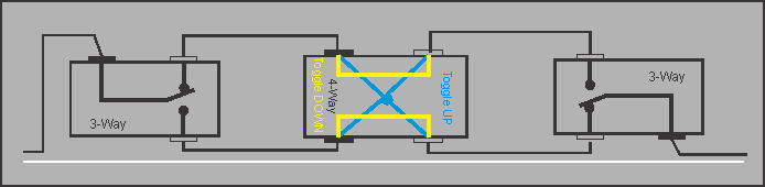
Note any number of 4-ways can be added to the middle.
So the above “switch” can be either:
- between power and the bulb.
- between the bulb and power
If at all possible wiring convention tries to put power on the black wire first, then Red wire second. Not all electricians adhere to this convention