I have a recessed LED at the top of my stairs and 3-way switches at the top and bottom of the stairs. I installed the LZW31 at the top of the stairs where the line comes into the junction box. After turning the circuit breaker back on, I noticed the LED was faintly on. I proceeded to manually program the LZW31 for neutral+dumb switch. LED still faintly on. I pressed the up/on button 1x and the status bar became full/bright blue but the LED in the ceiling did not change – it remained faintly on. I pressed the down/off button 1x and the LED turned on briefly at full brightness, then it went back to faintly on and I heard the switch click. I flipped the dumb switch at the bottom of the stairs and the same thing happened – LED turned on full brightness then off and the LZW31 clicked.
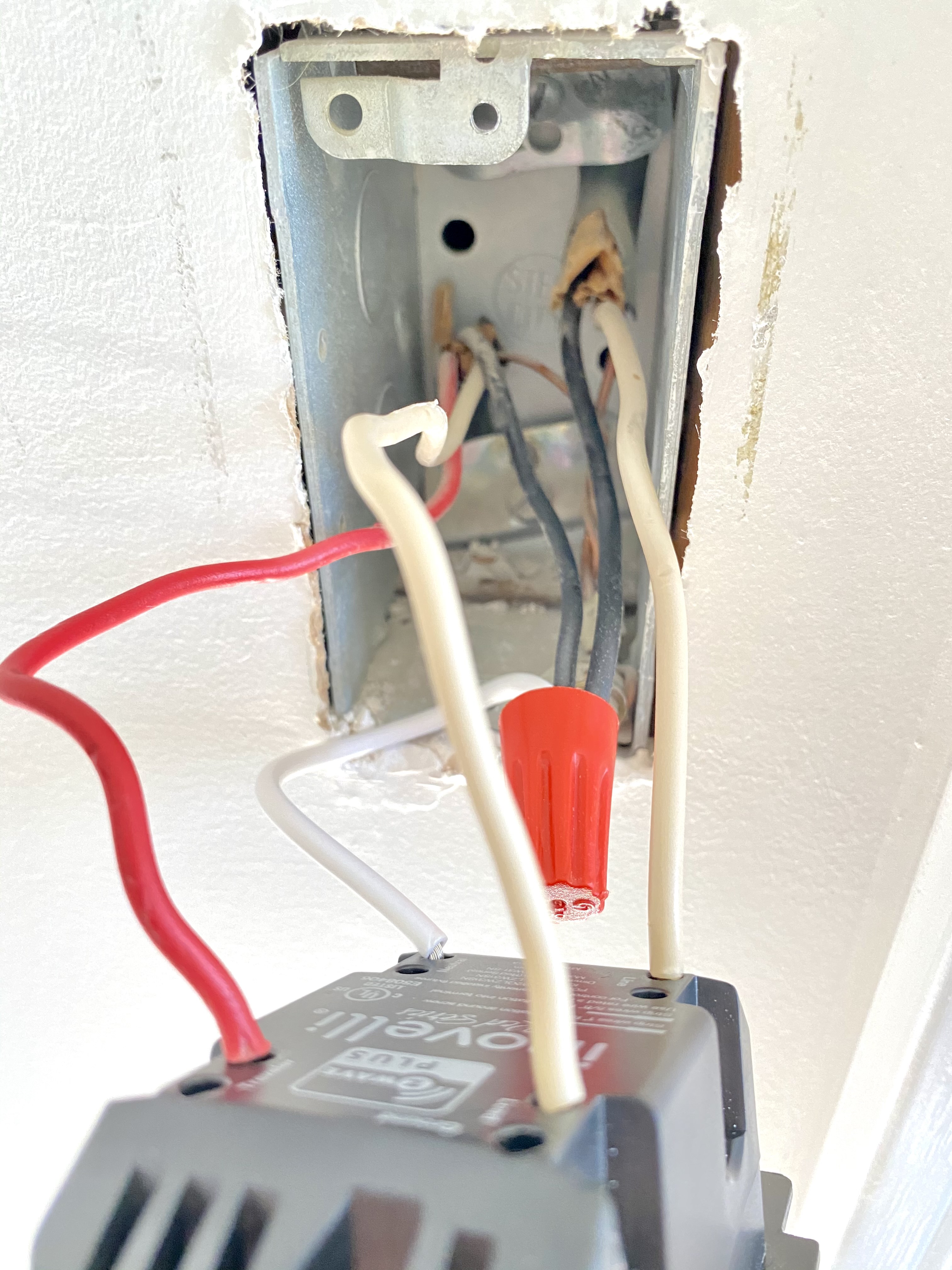
Here’s a photo of the box at the top of the stairs with the LZW31 wired:
Note that the black wires in this box are the neutral. They were wired together behind the existing 3-way switch and I confirmed that the white wire coming from the 2-wire cable in the upper right side of the box is the line with a non-contact voltage tester.
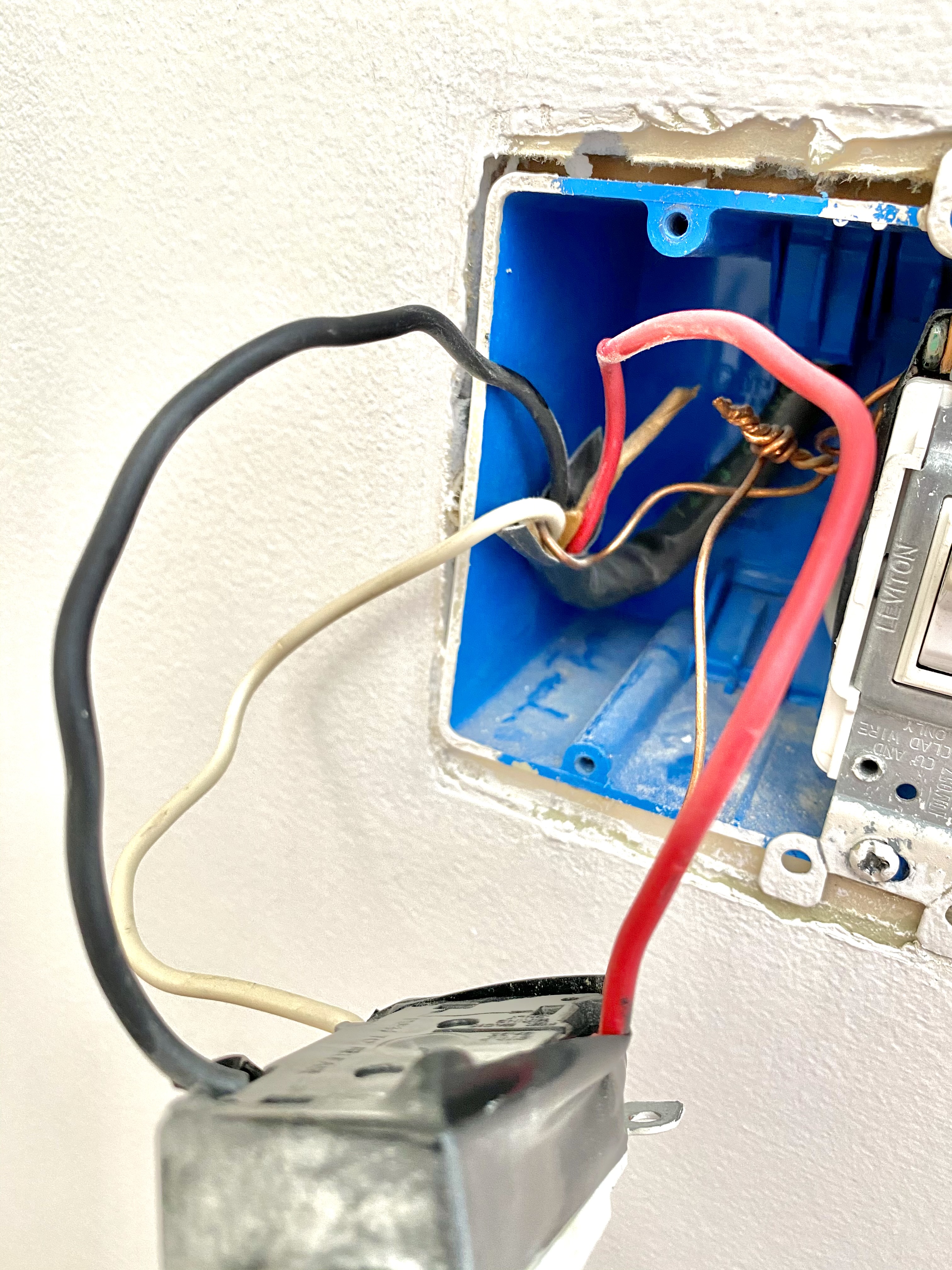
This is the box at the bottom of the stairs with the dumb switch:
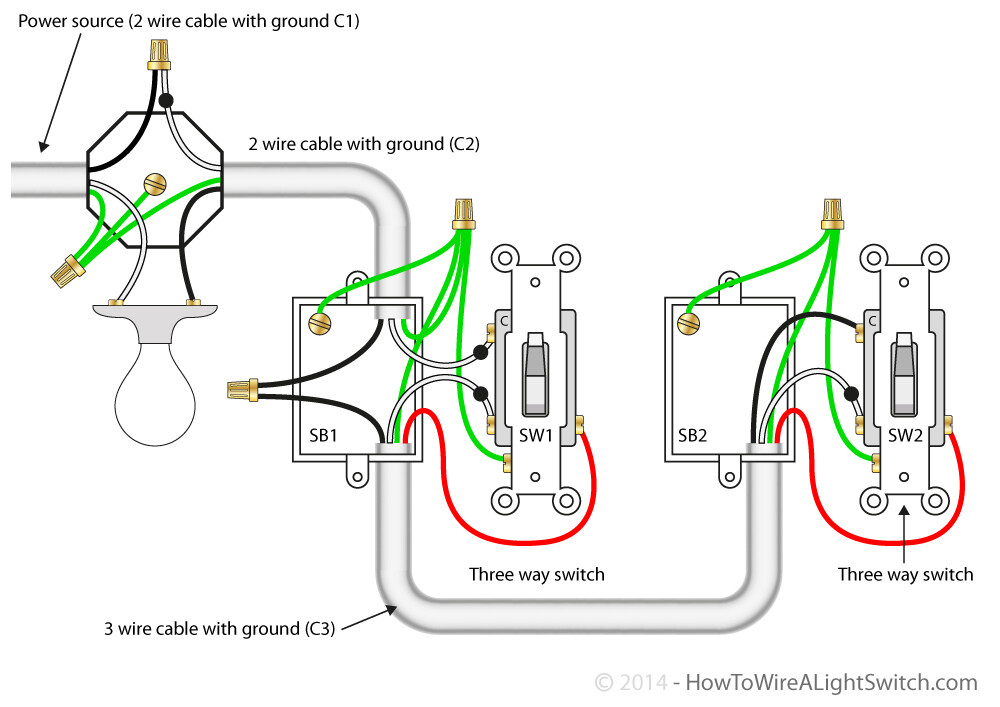
The house was built in the 70’s so maybe the line actually goes to the light first, then the top switch (hence the reversed black and white wires from normal), then to the bottom switch? If that’s the case, and the line is not in either box, I guess the LZW31 will not work in this arrangement.
Or is this more likely to be an LED compatibility or parameter settings issue? Any ideas or suggestions would be greatly appreciated!
I think this supports my theory that the line goes to the light first, then load goes to the top switch, and then the bottom switch. How fixable would that be?
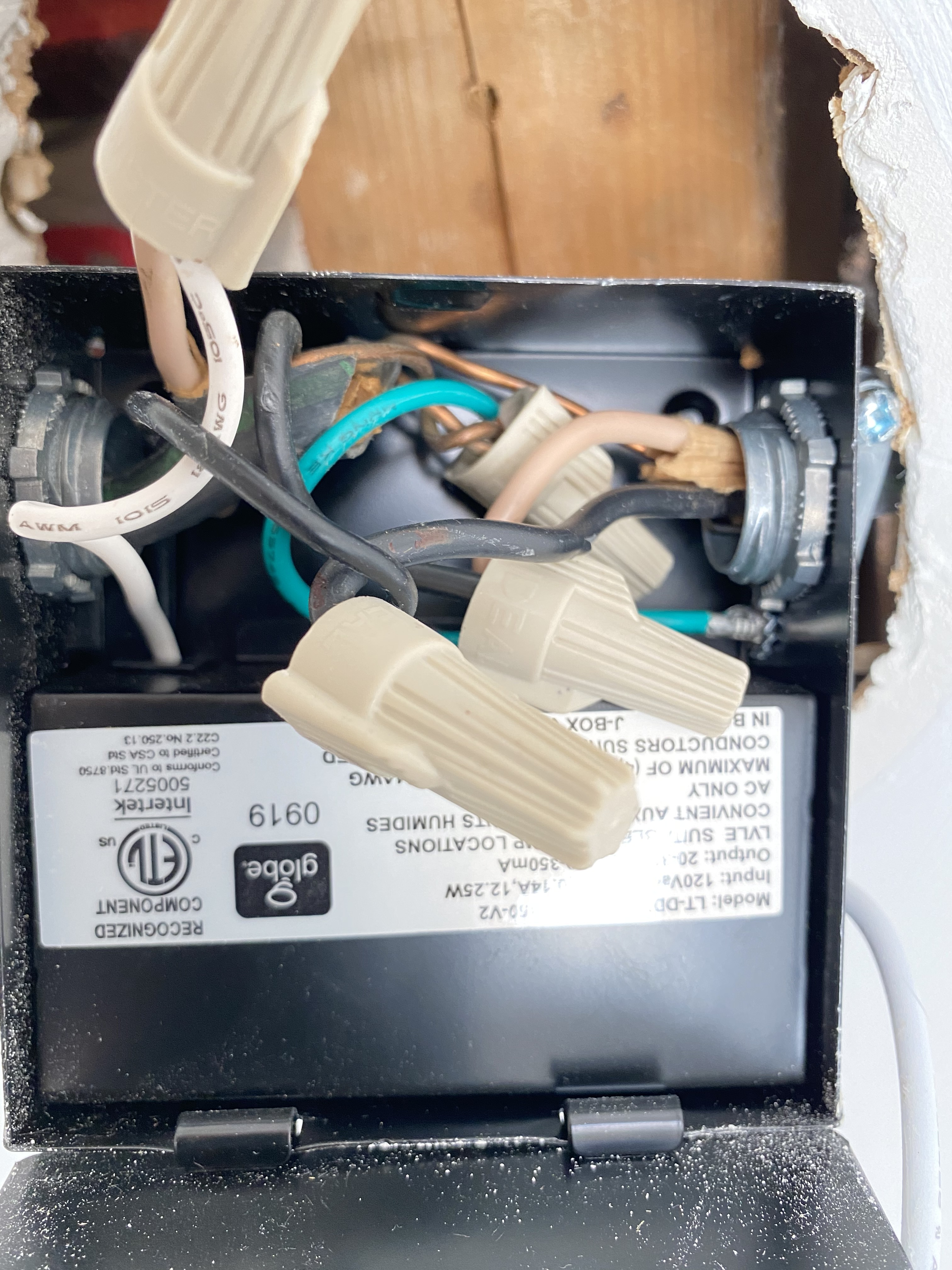
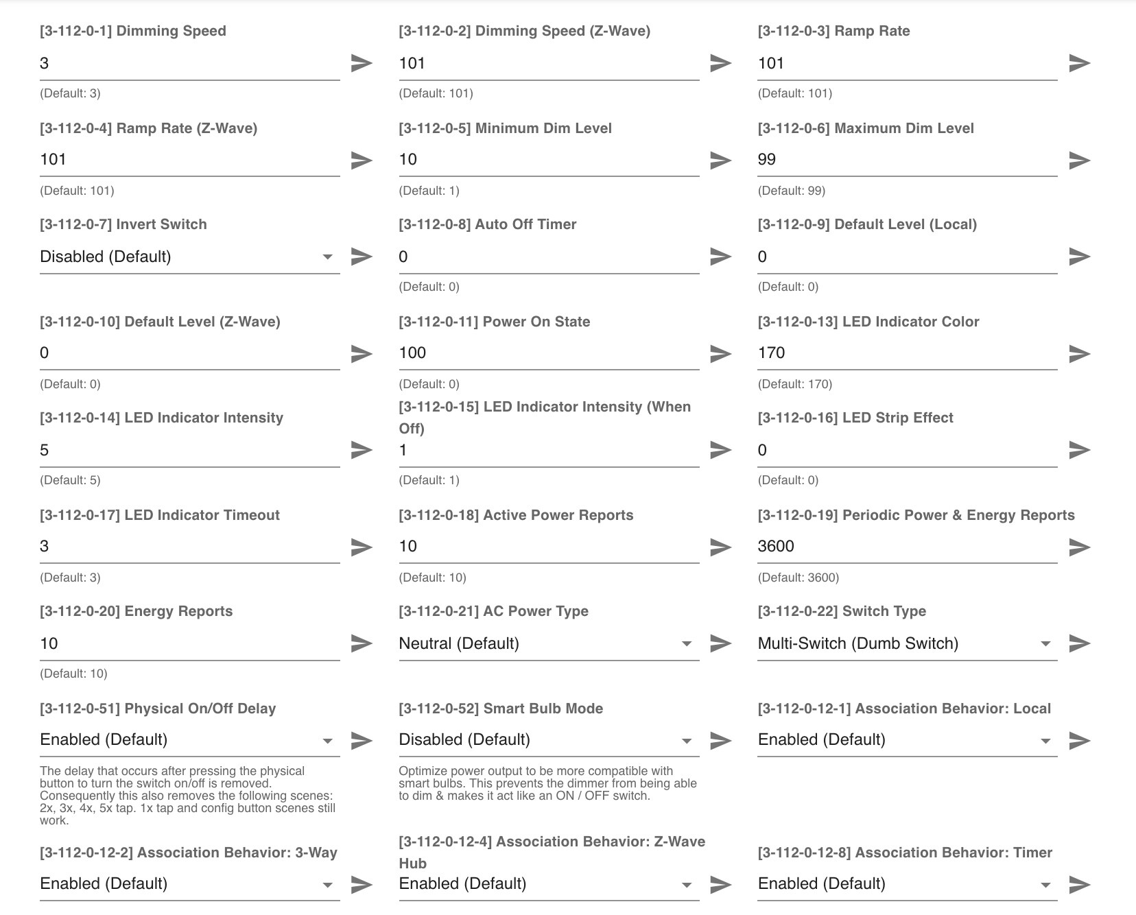
Here’s the info on the LED itself and a screenshot of the config parameters.
@Bry you are one of the wiring experts here, have you see any successful installs with line to the fixture first? I know the inovelli needs line, but could his be reworked?
The Line to the fixture first generally isn’t a problem, presuming you understand how it’s wired. That usually results in a non-neutral at one box. Adding an Inovelli and an Aux shouldn’t be too difficult, normally.
I’m not yet 100% sure what is going on here. Looking at the two switches alone suggests to me that there is power to the light first. I can’t see the light box well enough (is there only one and pull out the wires so the connections are clear), so at this point here is what I see based on the switches.
In a power to the light first, you send the power to the first box usually over the white of a 2-wire, so a white being hot isn’t unusual. The black of that 2-wire is usually the load. I know you called it a neutral but just because it’s not hot doesn’t make it a neutral.
So carrying on with the traditional wiring, you send the hot from that first box over the black on the 3-wire to the other box. There, the black is connected to the common terminal, where the red and white travelers switch the power back to the first switch. Your picture has tape over the screws so I don’t know if that’s how it’s wired.
So how do you tell if I’m correct?
1 - Pull the wires out in the light box. There should be two 2-wires. One of those two will be a constant hot and neutral from the panel. The other 2-wire is going to the first box. The white of that 2-wire is connected to the black on the panel 2-wire, and the black is connected to the light. The which from the panel 2-wire is connected to the other terminal on the light.
2 - If that looks good, in the “Inovelli” box, remove the two conductors from the 2-wire. If you touch them together, you light should illuminate. (Or it will pop the breaker if you have something else going on.)
What I’ve described originally looks like this. Do you have pictures of the original switch in the "Inovelli " box before you removed it? Pictures of the other switch without the electrical tape would be nice too. Also of the light box with the wire nutted conductors pulled out to see the connections.
I honestly can’t tell but at first glance, I don’t see a neutral. The 14/3 looks like load, traveler, and COM coming back to the light. Thus the wiring is not right. Looks like non neutral setup. We need more data as @Bry mentioned above.
I confirmed before I put everything back in the walls/ceiling that the circuit is indeed wired the same as the diagram above. Sorry the photos were unclear. The terminals on the switches were no help – they were all the same color with no indication as to which was the common.
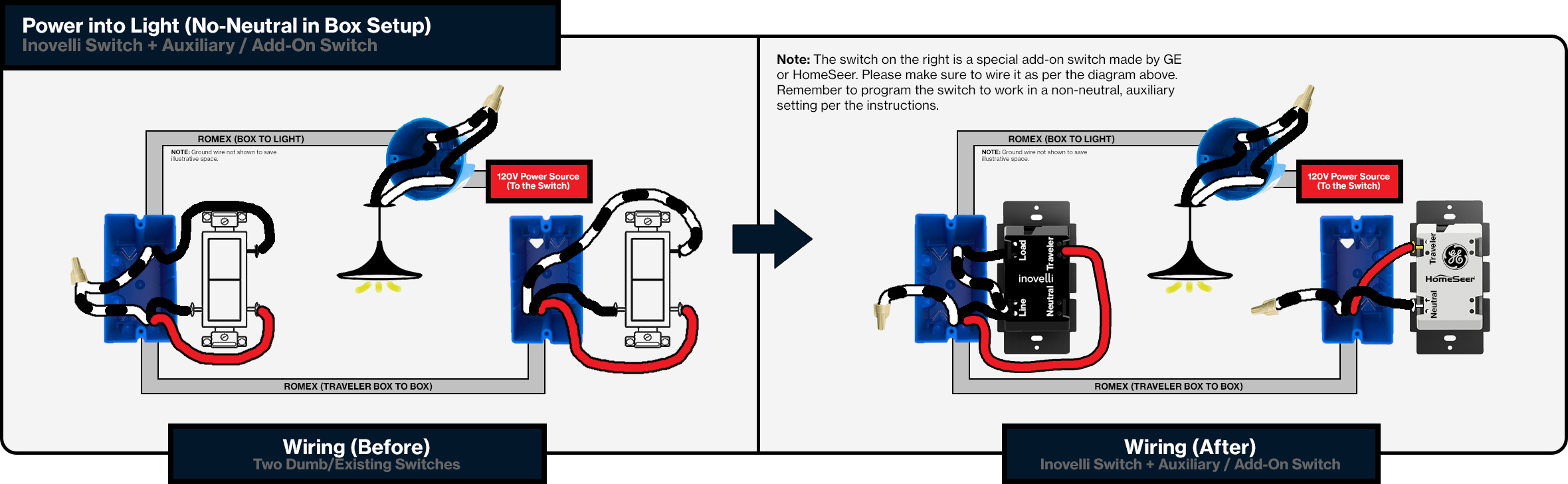
Inovelli Support said I should be able to wire the dimmer in a non-neutral configuration with an add-on switch, like this:
I would need to add a bypass to the light since there is only one 12W LED on this circuit. I’ll report back here if/when I get this set up. Thanks all for your help.
It’s in the non-neutral section at the bottom of the Gen 2 Dimmer Diagrams. If you pulled the switch (vs dimmer) diagrams to look, you won’t find these because the switch requires a neutral.
Just wanted to follow up and say that this wiring setup worked for me. So if you have line power going first to your light, then to your multipole switches, you can install the LZW31-SN in the first switch position and an aux/add-on switch in the second. I used a GE Enbrighten add-on and to my surprise, it actually works as a dimmer in addition to turning the light on/off.