I’m hoping someone can help me out here. I’m looking to replace the left switch in a double switch situation. The left switch has a push in for its line, but also a separate screw in that leads to the other switch’s load. I tried to connect both to the smart switch (red series on/off), but the push wire would just fall off. Does anyone have any ideas on how to make it work? Thanks in advance!
So if I understand you correctly, you have 2 conductors, presumably the same gauge, that you need to connect to one terminal on the Inovelli.
You will use both back-wire holes on the appropriate Inovelli terminal for this. Start by loosening the screw. If you look down into the back-wire holes and move the loosened screw back and forth, you’ll see that the screw is attached to a backing plate. When you insert the conductors, you want them to go between that backing plate and the outside of the switch. So then when you tighten the screw, the backing plate is drawn toward the outside of the switch, holding the conductors in place.
If your conductors come out easily after tightening the screw, then you likely had the conductors on the wrong side (closer to the center of the switch) of the plate. If that’s the case, the backing plate won’t hold the conductors snugly.
Your ‘dumb’ switch push-in holes work a little differently than ‘smart’ switch push-in holes.
The dumb switch has a locking spring so you can just push in the wire and it locks in place. Then you need to insert a small thin screwdriver into the slot to release the wire from the locking spring. With this type, the screw does not need to be tightened
Like Bry explained, the smart switch uses the screw and backing plate to grab the wire instead of the locking spring. So on the smart switch you still need to tighten the screw after inserting the wire to hold it in place.
Thanks for the replies. I’m just a little confused on what I should do with the screw in wire.
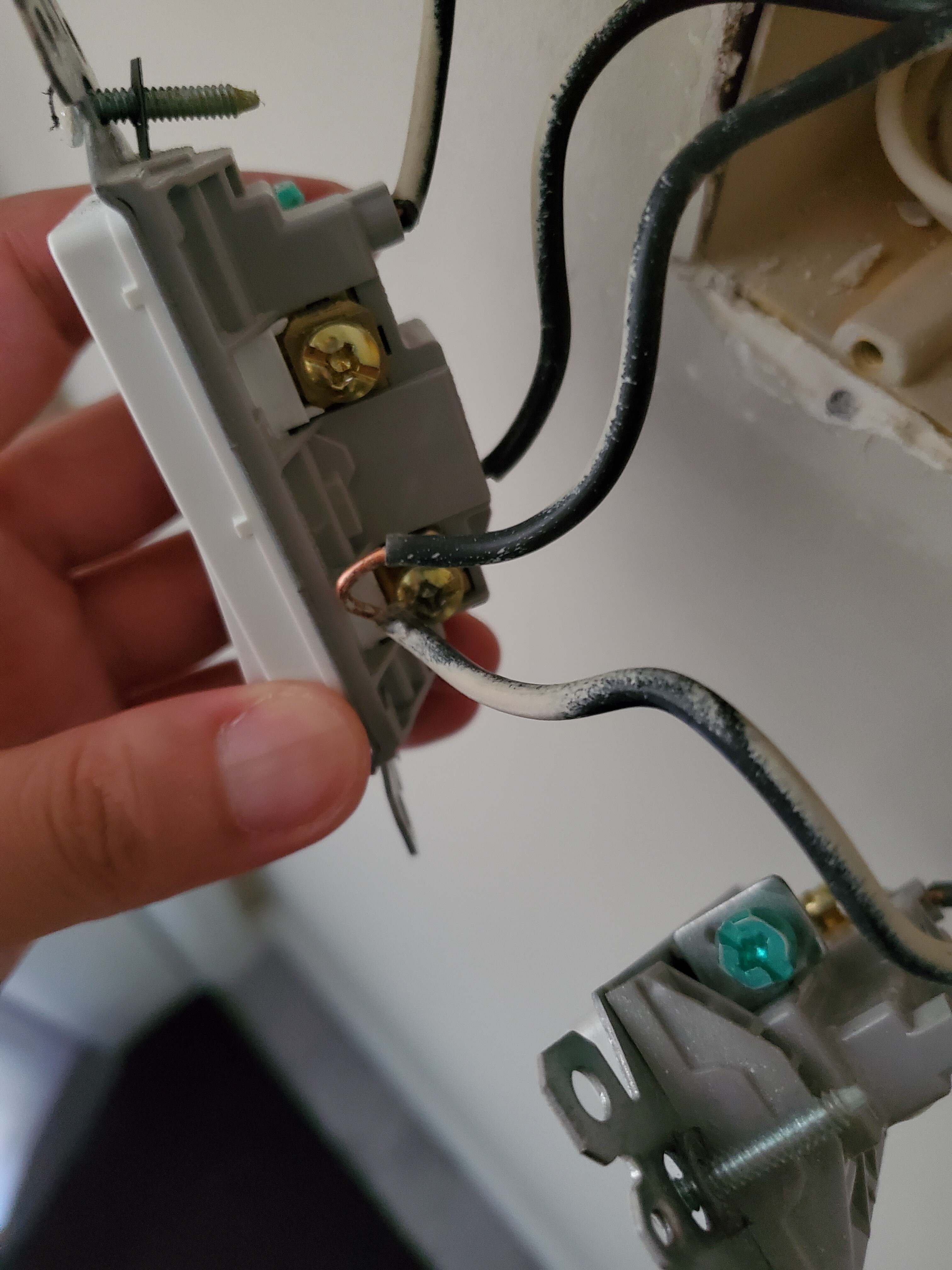
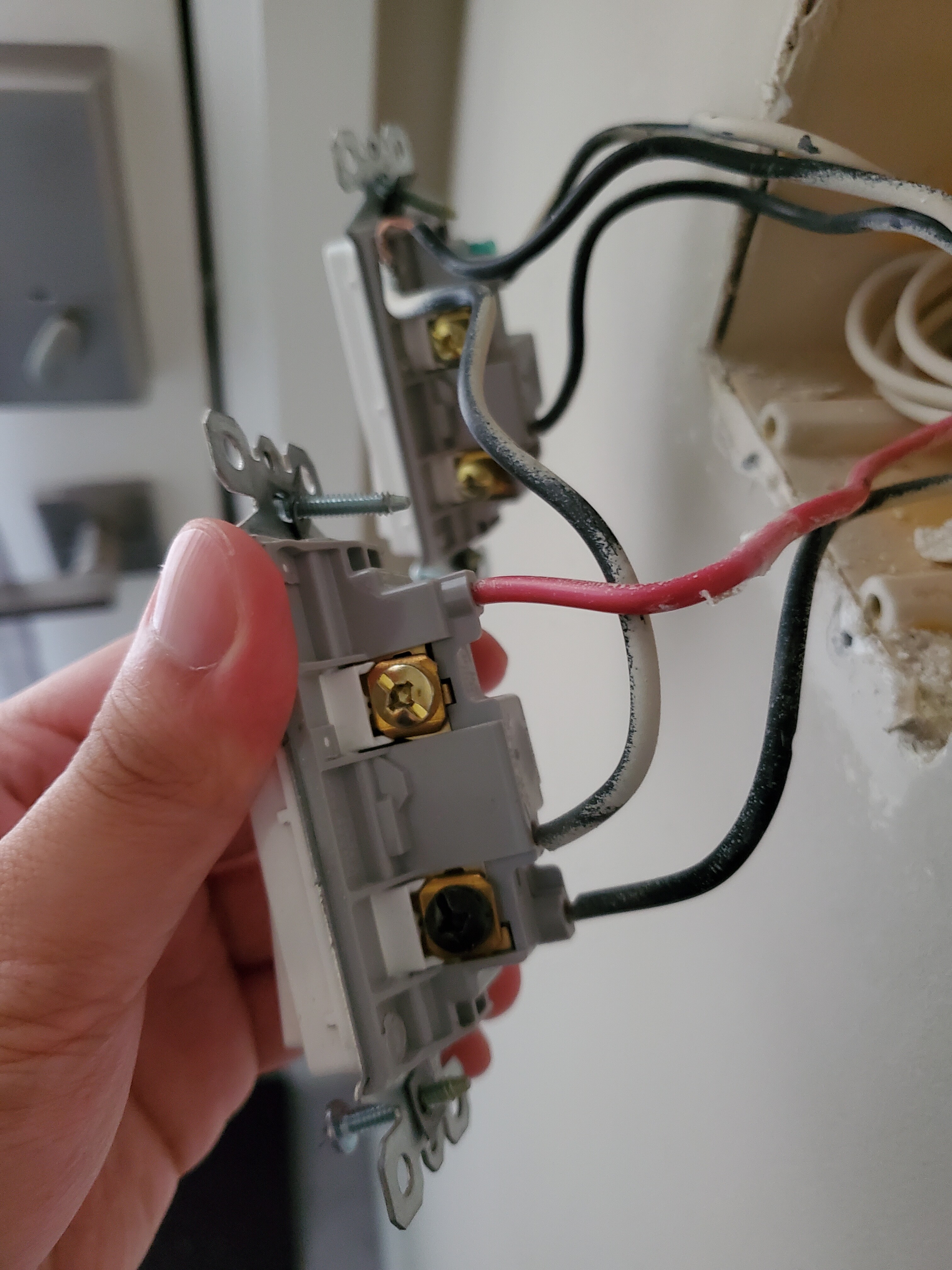
The 2 wires closest to the bottom screw are actually 1 wire, one end goes in the wall, the other end goes into the other switch. From what I can tell (I’m no electrician), that wire provides no power. I say this because I tried using the other switch without hooking the wire with the screw and the light doesn’t turn on. My theory (again, I’m no electrician) is that the line from the first switch (the one I want to replace) feeds power from the push in to the screw in, which then goes to the other switch. I have no way of proving this, so I’m wondering what my next step should be.
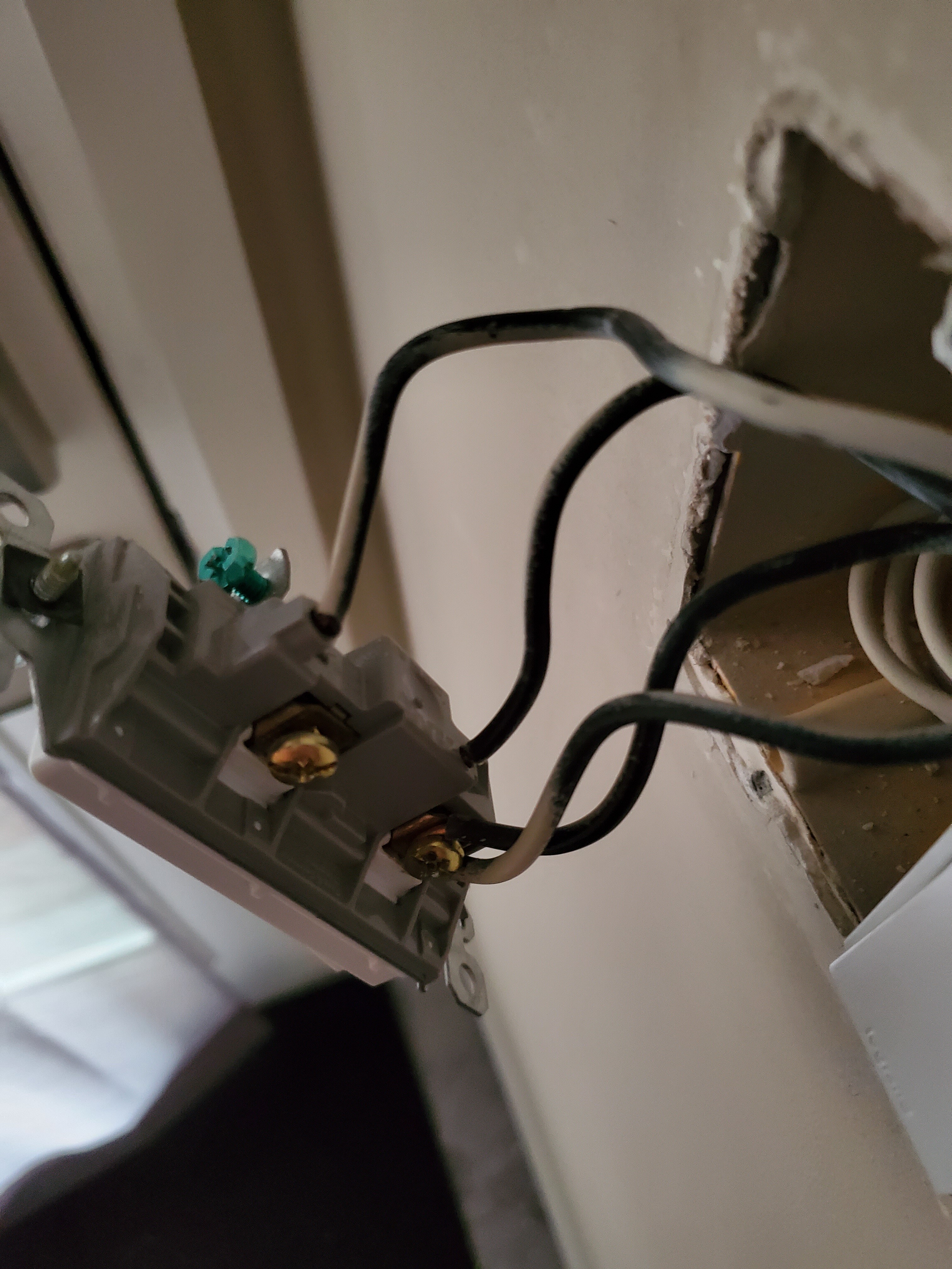
This is the wiring for the switch I want to replace. The top push-in is the load, the bottom push-in is the wire. The hook wire (the one I’m confused on) is a line for the second switch (I unhooked it for the photo).
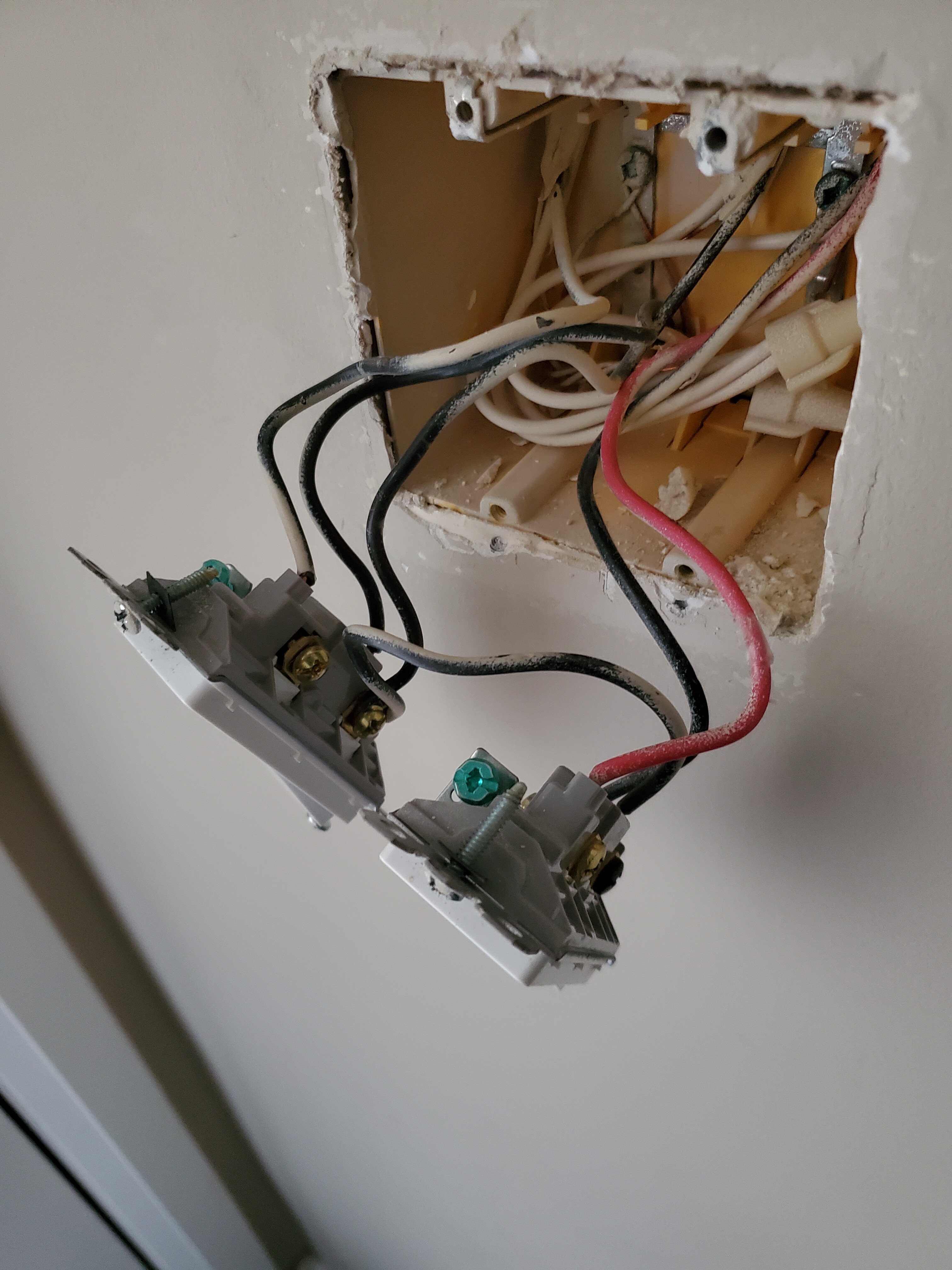
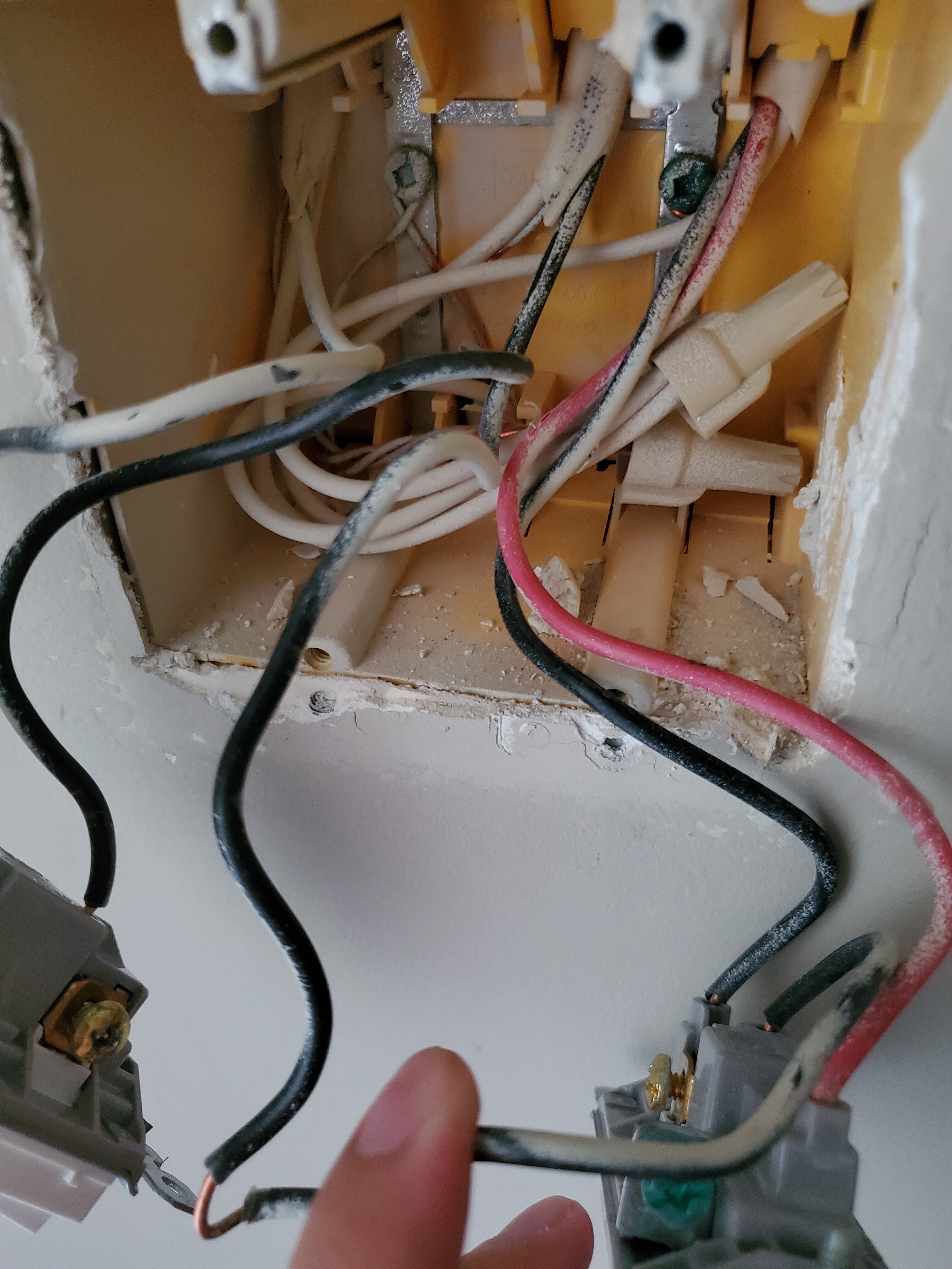
This is what the gang box looks like. Kinda hard to see where all the wires lead to, but the line for the first switch (to be replaced) comes from the bottom, while the line for the second switch (the hook wire, the one I’m confused on), comes from the top.
My question is what to do with the hook wire. I can’t hook it onto the Inovelli switch, so what are my options for it?
That didn’t work… I also read the wiring guide for the other switch (it’s a 3 way) and noticed that it said there are 2 travelers and 1 hot… I’m assuming that means no load? I’ve given up on it, thanks for all your help.
Maybe you should get someone to help because that really isn’t a very difficult wiring issue to sort out.
The same hot you can’t figure out simply goes to both switches. The 3-way switch not having the load connected has nothing to do with replacing the other switch. The black screw on the 3-way is the common and it simply has line power applied via that black wire.
Cut that loop and then use a Marrette to connect those 3 wires together along with another piece of black wire. Tuck the Marrette and extra wire into the box and then connect the new black wire to the Inovelli.
I thought about doing that, I’m just not 100% sure it’ll work and I (obviously) can’t undo the cut. I already have Philips Hues for that switch, I can live with not having a z wave switch for it.