Help with 3-way installation on a double gang box

Hi all,

I could use some help with a 3 way installation on a double gang box.

To preface:

I have three Inovelli Dimmer Switches.

2 switches are for 3-way installations with aux add on. (Using GE/Jasco Enbrighten). One for the hallway and one for the kitchen.

1 switch is for a single pole installation to control the back patio light.

Now, I’m still unsure if my house has a neutral wire or not ( not sure if this is overall wiring, or dependent on wiring in switch box). House was built in 1970 of that’s any help.

However, the reason I’m prefacing this is because I have some older GE smartswitches that work well in single pole applications in my house and I’m pretty sure they required a neutral wire. I installed them years ago, so I’ve forgotten their wiring pattern. I just followed the instructions. They were simple and they still work.

However, I wanted to use these Inovelli’s in more complex wiring such a 3 ways and also was intrigued that they didn’t require a neutral.

I started my project with my hallway 3 way lighting and it seems pretty straightforward. This is were it get tricky…I THOUGHT I had neutral wire, but after attempting to install the hallway lights with the neutral set up, they didn’t work, aux was not responsive, ceiling lght would come on dimly, etc. I even did all the parameters to configure the light for aux add on, etc. I then proceeded to post my issue in a Smartthings Group with pictures and many said my white wires were NOT neutral and that power was coming from the line directly to the light.

So I read on and found that perhaps they were right, because it seemed to be what I was dealing with based on the symptoms, if you will.

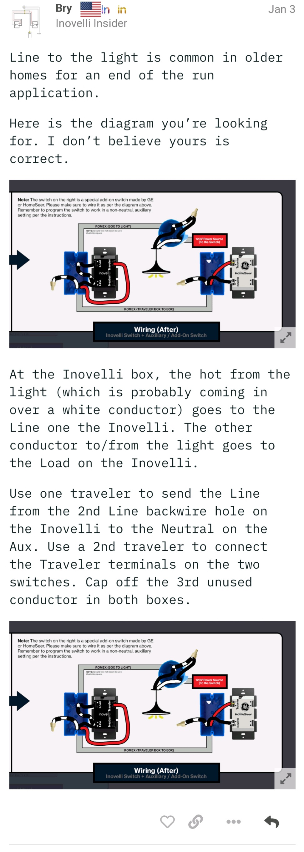
Anyway, I followed the diagram below from a previous user and Bry’s comment of "line to the light is common on older homes " resonated with me. So I followed the diagram posted below to the letter and lo and behold, it worked.

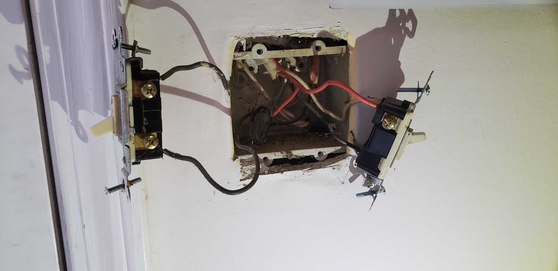
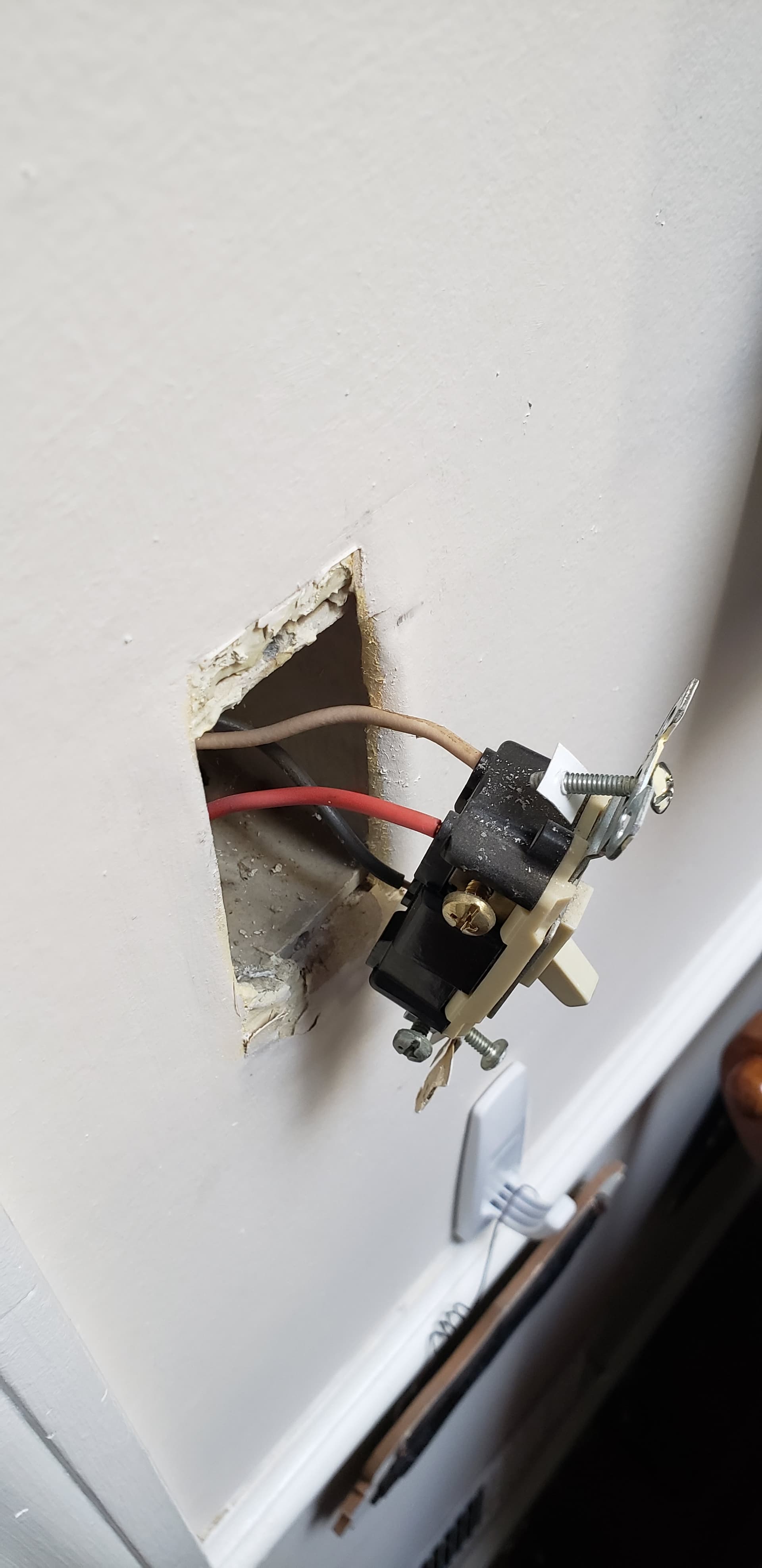
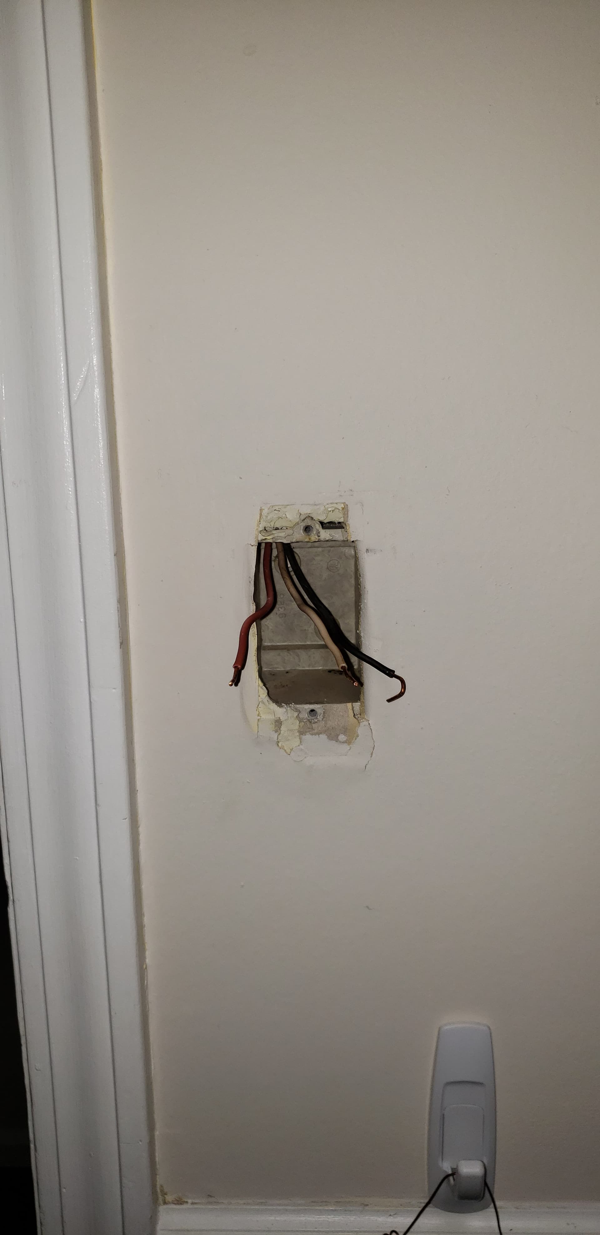
My first 3-way install complete…I got excited and figured the kitchen would be no different. After all one of the 3 way switch boxes (where the aux add on would go), looked identical with only the three wires, red, black and white.

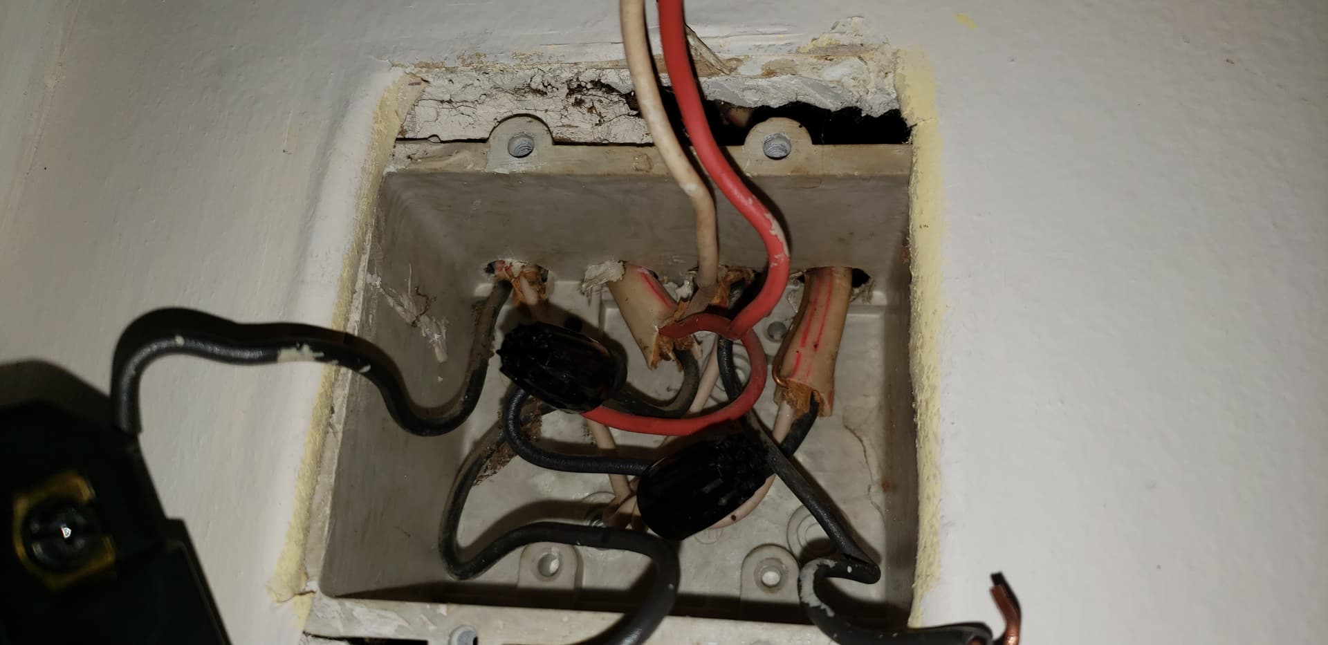
Well, that’s where the similarities end. The double gang box has me confused on the way set up with the black wires capped together and white wires capped together (which I’m now unsure if they are neutral or not as mentioned).

I tried wiring the three on what I thought would be correct, but ended up killing the switch. :frowning: So I had to buy a replacement.

Got the single pole one for the back patio working great though, I just think that I’m in over my head on this 3 way set up due to the "extra wiring in the double gang box. So I went to the home store and temporarily got me a cover for the Inovelli controlling the patio light and just put back the dumb switches for the kitchen 3 way as they were in the double gang box.

So in summary, these switches are great for single pole applications and I also don’t want to kill another switch and make the wife angry again and pay stupid tax by sacrificing these Inovelli’s.

So I’ve reconciled to hiring an electrician to put up my 3-way switch for the kitchen, though if I got 2 out of three Inovellis installed, seems kinda silly.

Out of the recommendation of Eric at Inovelli though, he mentioned there might be some fine folks that could help me out.

So I’m giving this a chance before I hire a pro for just one switch. :slight_smile:

Thanks for reading. I know its long but I tried to be as concise as possible.

Thanks in advance for any help you can give.

-Alex


From what I can tell you have 4 romex coming into that box, from left to right.

  • a 2-wire, this is the load of the left switch so nothing to do with the 3-way.
  • a 3-wire, this wire goes to the other 3-way switch.
  • a 3-wire, this appears to be the load for the 3-way. red = constant power, black = switched and white = neutral
  • a 2-wire, this appears to be the line power.

Seeing this wiring, is it switched receptacles or feeding a fan or something like that? It’s seems the 3-way circuit is feeding a load that needs constant power and switched power. Can you confirm a reason for the load having both a constant and switched hot?

The wiring diagrams you posted don’t match what you have here. This is how I believe it should be wired.

2-switch box
The capped white and black in the box is the neutral and hot to the switch.
The red on the left 3-conduction will be the traveler to the switch.
The white on the left 3-conductor will connect to the neutral.
The black on the left 3-conductor will be disconnected and capped.
The black on the right 3-conductor is the load to the switch.
All others in this box are left wired as is.

single switch box
white and red go to the aux switch and black is capped.

If you want to list what you did with each wire, we can compare.

Hi Peter, thanks for the feedback.

What you state seems to line up. Sorry the pictures were poor before. I’ve taken new ones now (taking pics of wiring is hard when there’s poor lighting lol) and I hope these help. @Bry could you please confirm if the above wiring steps is correct? I really don’t want to short out another switch. :slight_smile:

The 3-way switch only controls one light kitchen as you can see.

Question: Are the white wires that are capped neutral? I had similar capped white wires in the highway light and was told it power from the light and not neutral.

So I’m confused (clearly I’m no electrician).

Is it normal to have neutral wires in some boxes and not others? House is from 1970, so not sure if that makes a difference.

So far until I’m certain, I’ve held off on wiring the 3 way switch with the Inovelli just because I don’t want to blow this one. ( I already killed one here and had to get another out of pocket to replace it.)

Thanks for your help!


I will take a look. I don’t usually jump in on a wiring thread when someone else starts to help, unlike some others. But since you asked I will.

The first think I would have suggested to you is that you need to test with a meter (not just a non-contact sensor). A physical inspection of the wiring only gets you so far, and assumptions and electricity don’t mix well. :worried:

So without measurements, I can’t absolutely confirm. I’m also a bit confused about the 2nd 3-wire in the double gang box. My thinking is if the 2-wire on the far right is going to the light and the 3-wire to the left of it is going to the other switch, then the other 3-wire isn’t involved and the source of the hot is yet undetermined. That two wire may be feeding a hot, but you won’t know without testing. And if it is, then the 3-wire is passing through the light, so this is a bit more complicated.

If you are not comfortable working with a meter on live wires to measure, then as you were thinking, an electrician may be your best bet.

@harjms . . .

Yes, you can have a mix of neutral and no neutral in boxes. It is more likely to find neutral wires in boxes with more than one switch. Then, it can make more sense to the electrician to wire the power into that box and branch from there to the other stuff.

Tell us what you tried to do?

Also, the left switch did you just wire it with no-neutral?

The 2 conductor on the left is going to the outside light using the left side single pole switch/dimmer. It’s not part of the 3-wire circuit. Nothing else makes sense for that light and switch. That means the capped black wires have to be the line because they are powering that switch.

The 3 conductor on the left has the white and red hooked to the traveler terminals of the 3-way switch. So we know that it is going to the other 3-way switch box.

The line and neutral could be coming in on the red and white of the right 3-conductor or on the black and white of the right 2-conductor. It doesn’t really matter, the red + black and white + white are capped together. This means the white group capped together pretty much has to be neutral. Nothing else makes really sense for those.

If you want to start simple, try the switch in single pole mode only connected between the group of capped wires and the black on the right 3-conductor. If it works, then you know those wires are the line and load. It should be impossible to damage the switch doing that.

Agree. Probably need to start with a DVM to find each leg. From the first picture, the capped upper left looks like line; other capped is neutral, but that’s a guess without seeing all sides of the wires to see if they all go into the bundle or not.

Also, please wire your grounds together while you’re in there.