Help with 6-way wiring

Trying to wire up LZW30 and I can’t find the first switch position. These are hallway lights that are controlled by 5 different switches upstairs and downstairs and powered by a subpanel upstairs. I’ve found a switch each upstairs and downstairs with 3 wires coming from a single Romex.
Downstairs:

Upstairs:

The other three switches (2 upstairs and 1 downstairs) have 2 white and 2 red each.

Upstairs 1:

Upstairs 2:

Downstairs:

The wires on the last switch go to the two leftmost Romex and the blacks from each are capped together.

Any ideas on where to put the switch and how to wire it?

Not sure if it helps, but I tried wiring up a switch to the lights on the other end of the hall. This replaced the right-hand switch in “Upstairs 1”. It won’t turn the lights on or off and when I flip one of the other switches (one had 3 wires from a single Romex and the other had 2 red and 2 white) it seems to toggle power to the LZW30. These lights are on the same circuit as the ones in the post above.

Honestly, with that many switches at play, I am uninstalling all of the switches (after labelling) and using a multimeter to find the hot when the breaker is turned on, then tracing each one out. It’s going to be REALLY hard to tell otherwise.

1 Like

Going to agree with @kreene1987 Probably need to find line and also determine if you have a neutral in the box where line is.

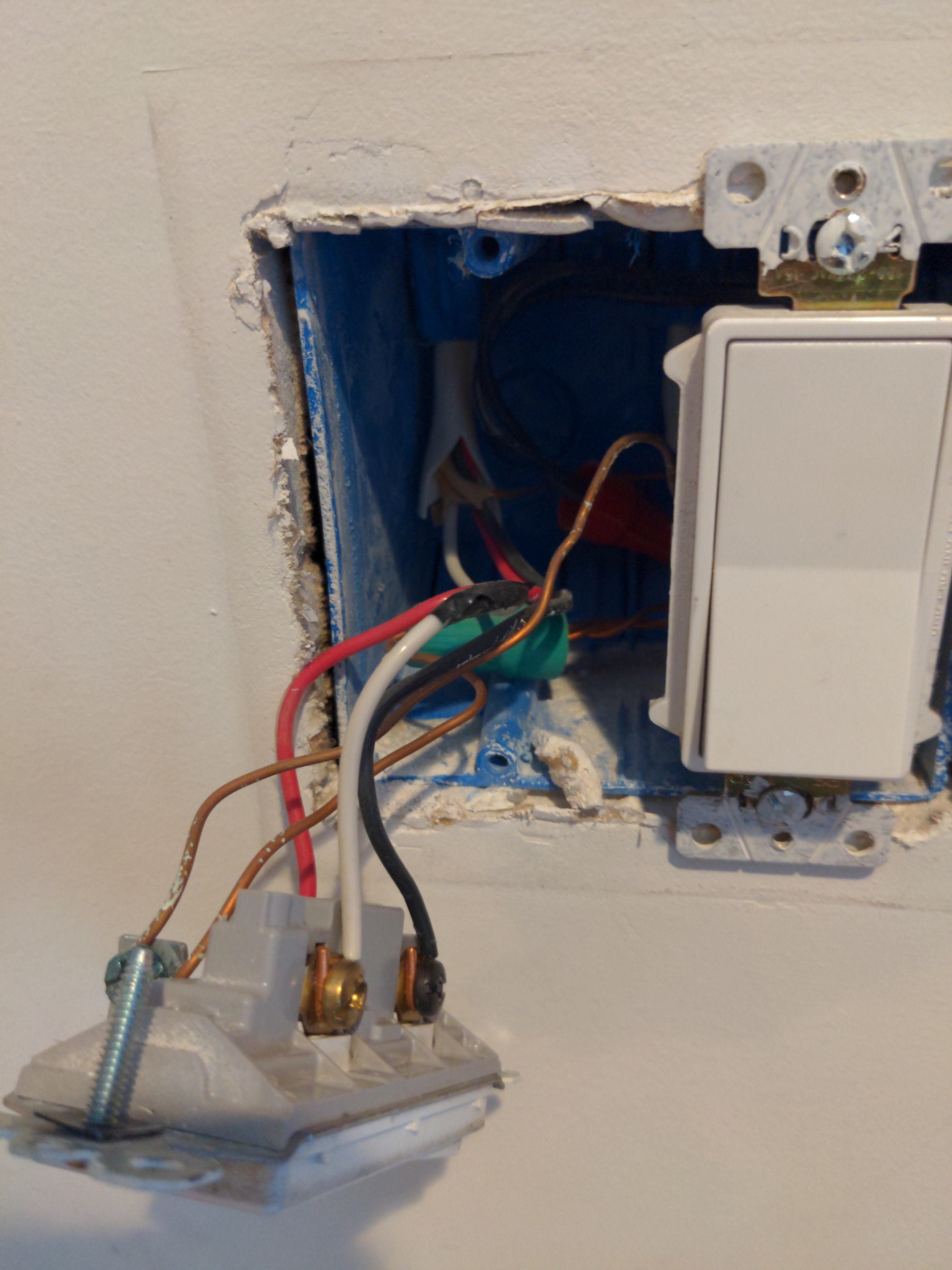
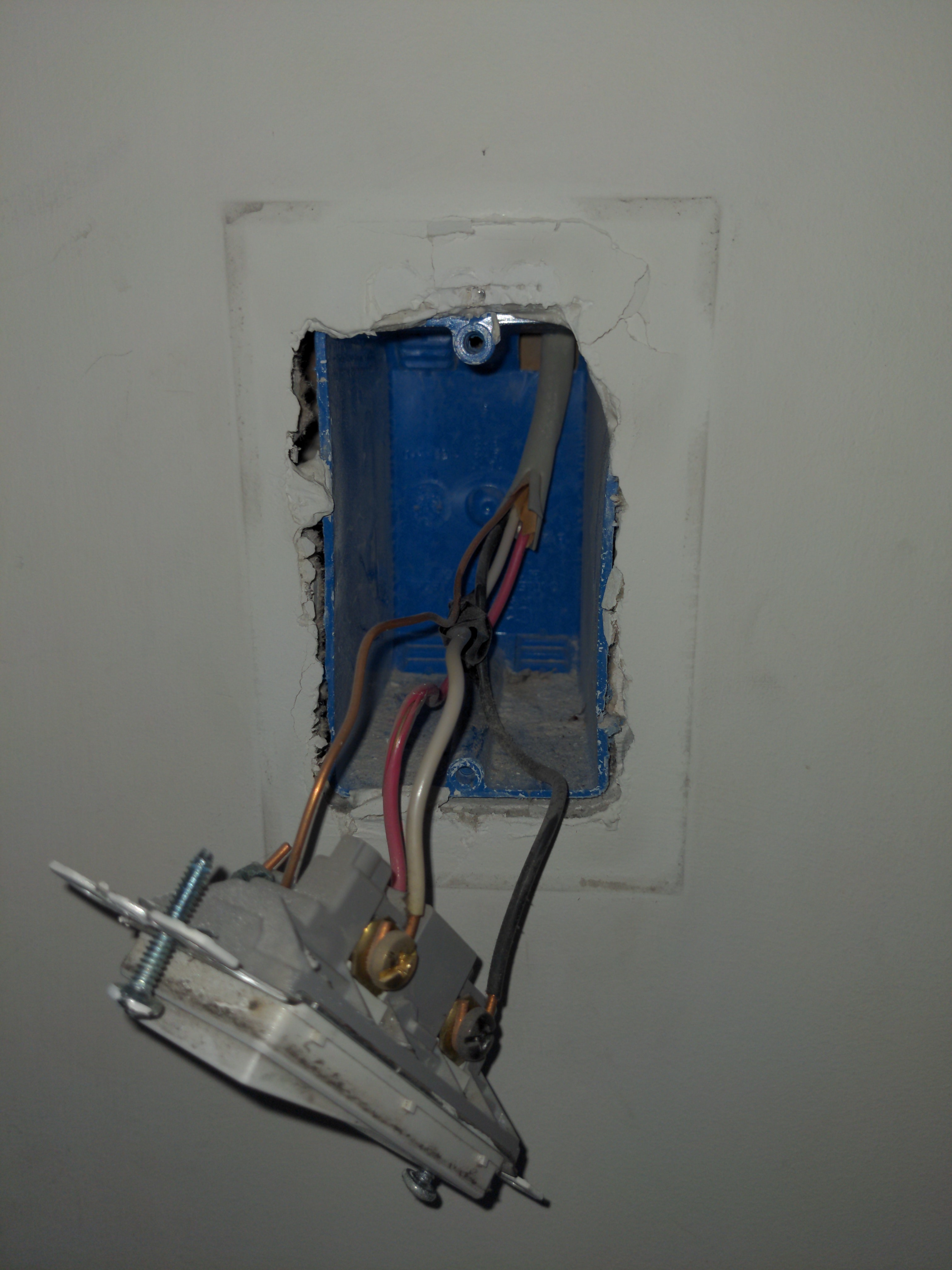
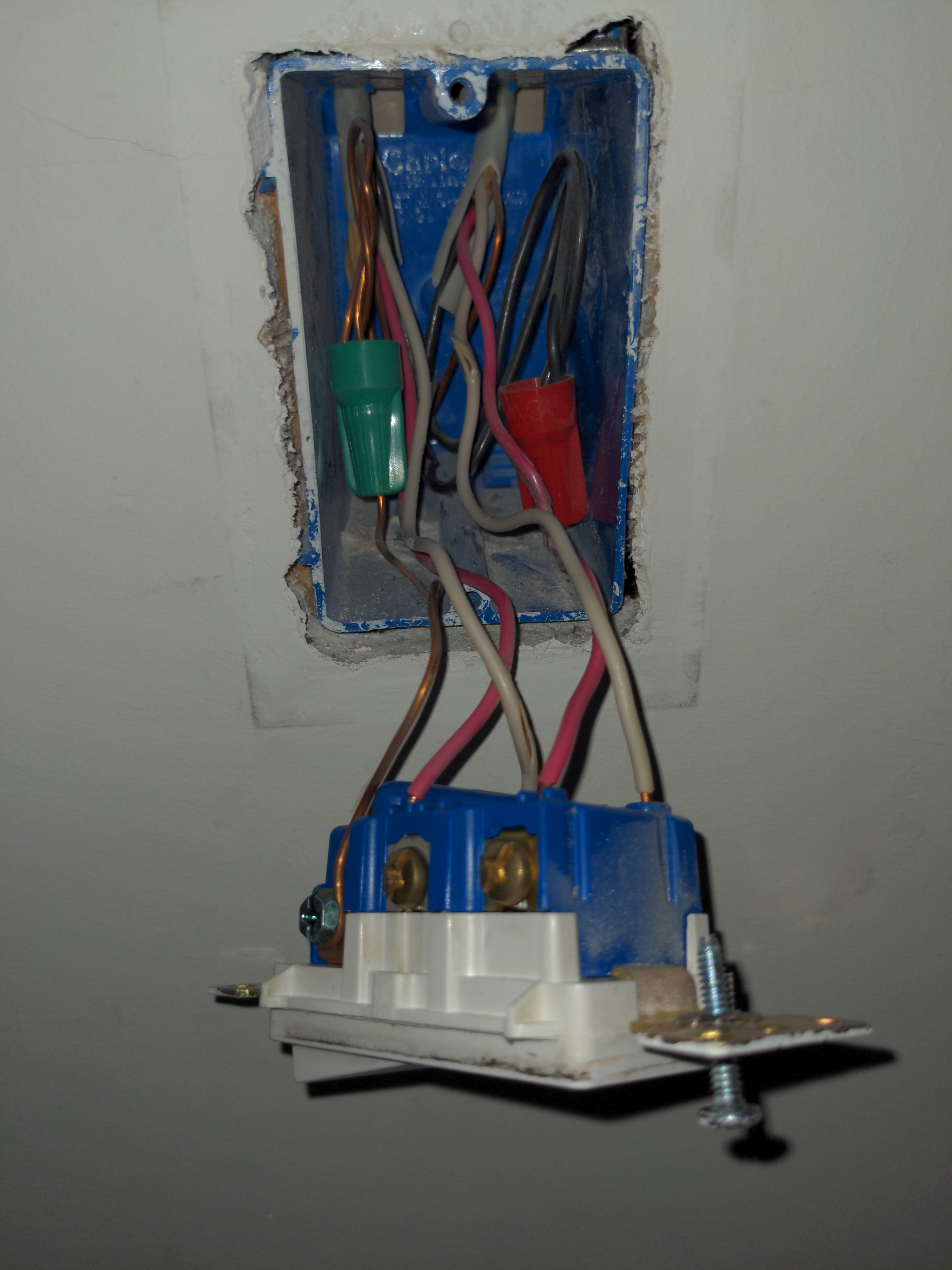
You’re going to have to take a closer look at the boxes with the 4-way switches.

In a more conventional wiring scheme, power is applied to one end and the load is either there as well or on the other end. In this configuration, it goes from a 3-way switch (three conductors plus a ground) to 4-way switch(es)(four conductors plus a ground to a 3-way switch. But in this configuration you are going to have more than one 3-wire Romex involved at the 3-way switches. By “involved” I mean more than one Romex at least partially connected to the 3-way switch.

Looking at your 3-way switches (and you should confirm) it’s pretty clear that all three conductors attached to each of the 3-way switches are all from one Romex. So what you don’t have if the more conventional wiring scheme I described above.

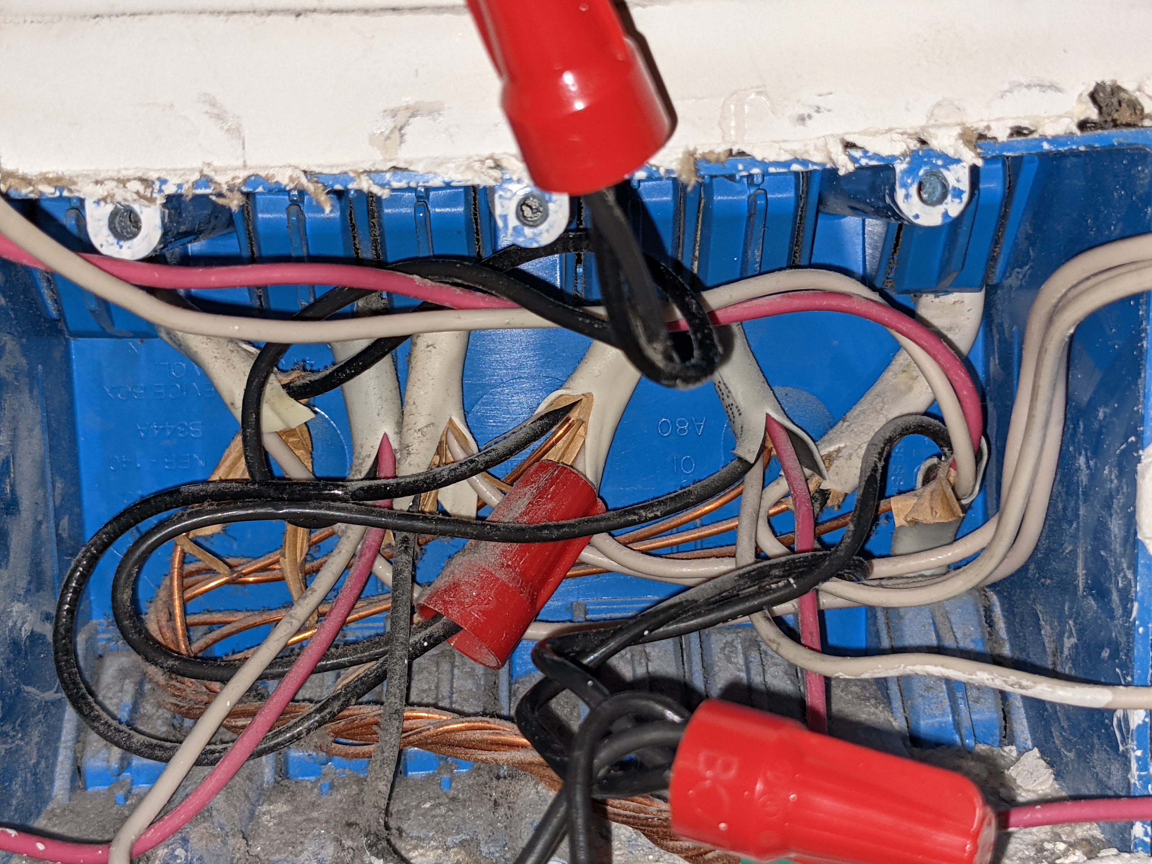
So that being the case, power is coming into one of your 4-way switch boxes. Going to copy/paste from another post to explain:

So if for both of your 3-ways you only have all three conductors from the SAME 3-wire Romex connected to them, then there are two possibilities.

1 - Power is being fed to the light first and then down to the 4-way switch. This will be a non-neutral at the switch box.

2 - Power is being fed to the 4-way switch box. This will be a neutral at the switch box.

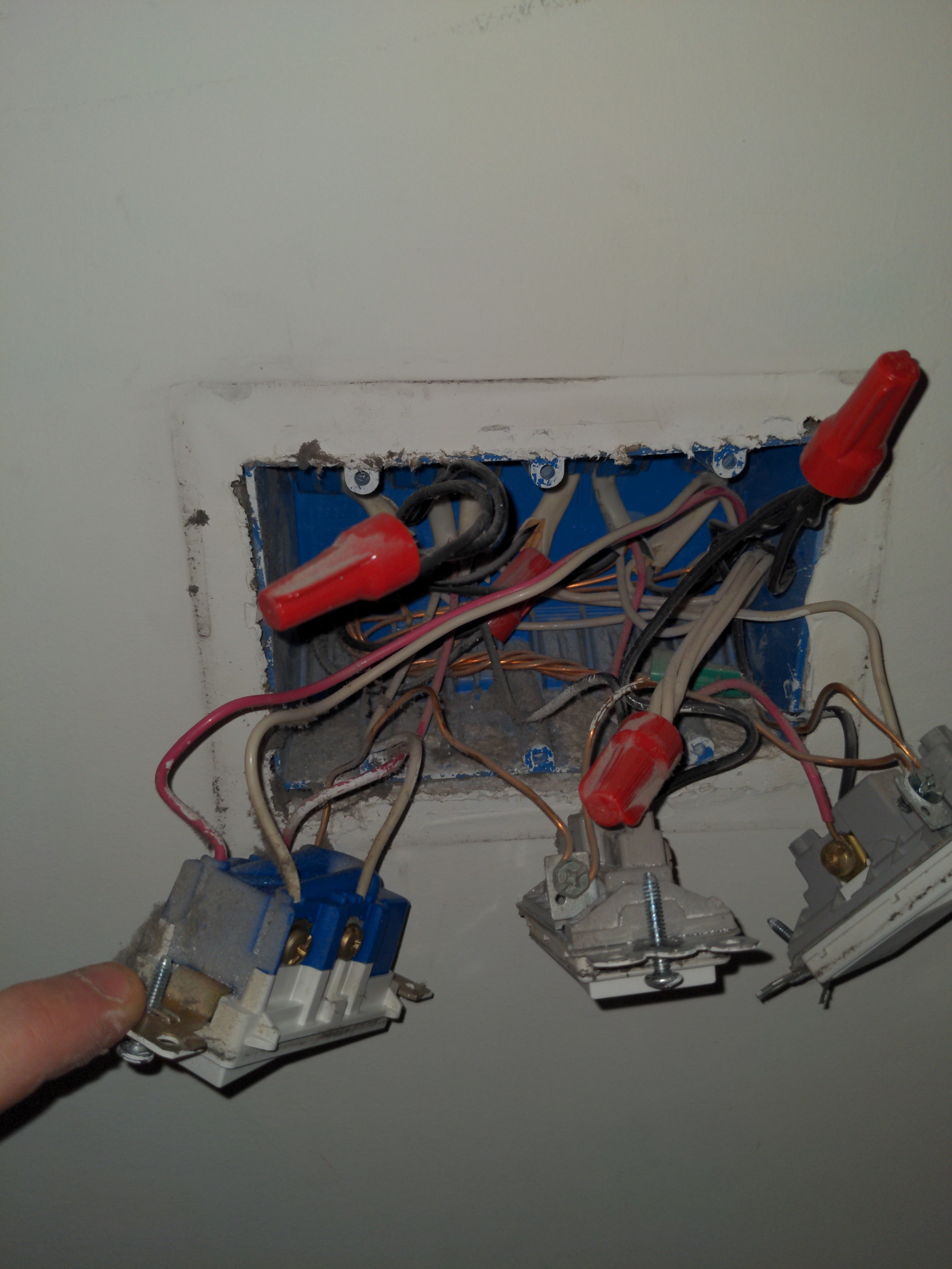
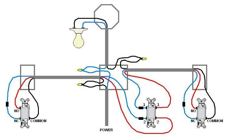
The way you can differentiate these is by the number of 2-wire Romex “involved” at the 4-way switch box, related to this switch leg. By “involved” I mean either connected to the switch or routed to the other switches. Look at the 2 drawings below.

In the power to the switch box, there are two 2-wire Romex involved. There is one for the incoming power and one for the light. In the power to the light, there is only one 2-wire involved, the one to the light.

POWER TO SWITCH BOX

POWER TO THE LIGHT
image

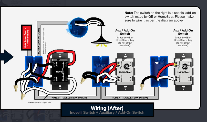
You are going to have to figure out which of these you have. Once you know which of these you have will dictate how it’s wired.

This can be a bit tough to diagnose. If you can get to the light (hopefully only one) you can look to see if it’s just fed by a 2-wire Romex or if power is coming into the light first. If it’s multiple lights or they are high hats, then it’s a mess.

Hopefully this is enough to get you started.

We’ll give this more thought.

Thanks so much. I’m going to open up the boxes after work and report back.

These switches control 3 high hats so I guess it’ll fall under the “it’s a mess” category.

1 Like

Ok, I think we’ve got a power to the switch box situation.

The 2 conductor Romex on the right feeds the bundle of black conductors that feed the 3 different switches in the box. Just to be sure, used a multimeter to test that the bundle was hot with all switches disconnected.

There are three different lights fed from this box and 3 2-conductor Romex one for each light. The 3 conductor Romex on the left and the one on the far right feed the 6-way system I was mentioning and the 3-conductor Romex on in the middle connects to a 3-way switch that feeds the 4-way system I mentioned in my second post.

Edit: Here’s a marked up version of the picture above to illustrate where everything is going.

Ok, thanks. I got most of what you described. The paragraph above edit made my head hurt, but I think you’re moving in the right direction. I don’t think this is one where anyone will say for sure, but I think you found the right box.

So if I understand you correctly:

  • The 2-wire Romex labeled “Power” seems to be the constant hot feed into the box.

  • The 2-wire Romex labeled “6-way” lights you believe is the switched to the lights. To test this, remove the black conductor temporarily and touch it to the black bundle you identified as the incoming power. If you are correct, your lights will turn on. Put the conductor back where it was.

  • I think you labeled things pertaining to the other/another leg, which is OK but distracting. There is a 4-way switch in this box which is in part connected to two 3-wires. I’m guessing that’s labeled “4-way switch” and pertains to the leg we’re wiring.

  • “4-way lights” and “3-way switch” are labeled for information but don’t relate the the 6-way we’re working on.

Confirm all of this please. Won’t be able to say “yep, that’s what you have” but I can give you a diagram based on what you say you have.

Sorry for the confusion. I think you understood me correctly.

  • Correct. That is the constant hot feed.
  • Tested. Confirmed.
  • Correct. I planned to wire that one as well, but it doesn’t pertain to this leg.

Ok, so presuming you have a Line and Load to the box you’re working in, the Inovelli will go there. You will use Aux switches in the rest.

The concept is simple. First wire the Inovelli and a simple 2-way switch and confirm that it’s working properly. Then, using the red hite and wwires of the 3-wires, send the traveler and neutral to each of the Aux boxes (use red for the traveler and white for the neutral). Cap off the blacks on the 3-wires as it’s not used.

1 Like

OK, so for this leg, I’ll need to to replace all of the dumb switches with less dumb switches?

Yes. If power came in to one end, you could use either. But when it comes into the middle, it complicates things. I’m not saying it’s impossible, but AFAIK no one here has figured that out.

The problem, basically, is that to start at one end you’d have to send the hot to a 3-way switch using one of the 3-wire conductors. But then you don’t have 3 conductors between the switches because you just stole one.

:+1:. Got it.

Thanks so much for your help.

1 Like

Just following up. I got the add-on switches and installed them. Everything worked like a charm. Thanks again.

2 Likes

Glad to help!